In reply to SVreX :
that's my caveat of "I might get some of these things wrong"... because: while I learned all this stuff, that was a while ago, and I don't get to go play with it "all the time"... so I might be rusty and get some of these terms/wrong backwards
i.e. I retain the right to be corrected by stafford, or another "aeromaximus" should they drop by
all that being said... this is a bit of my "wheelhouse" because I played around with airfoils in this regime for several design projects back in college

And Another Thing........ It Ain't gonna Fly, so really this exercise in Math Is in the A&P books and Like My Instructer said "You Can't remember All Of it but you have to remember which book it's In.
All these Beautiful Curves are , at 60 mph for naught, Yea sure at Steady State and over a distance you could Make things Happen , but all you need is your Sheet Of Plywood,
where you mount it has a lot to do with effectiveness, Roof height and over the Tail is best for simpleness about a 2" droped nose to tail will work with that metal at 30 deg.on back .Oops that's in the next Paragraph
You Didn't say how thick it was or what's left of the Sheet(4x8) 3/4" or better lends itself better for strength, Get a piece for Steps Called A Bullnose attach for the front of wing and at the rear about 2ft., cut a10" wide piece Street sign or washer/dryer side and bend in to about a 30 deg. angle and attach that to the rear, You can make it smooth but again Not nesassary. I Know that's crude and Pauls wing is as easy, But I Have a Bunch of aluminum sheets I scored when a sign shop Closed, and I will use wood for the frame and cover it w/metal
I'm Making one that is Pressure Sensitive, it will stay at A pre determined amount of Downforce from about 40mph up to 100+ It will lay flat at speed with an adjustable Flap , Not legal in sanctioned racing, but, CHALLENGE
SVreX said:
In reply to sleepyhead :
...although it did make me wonder what 5 year old is familiar with Reynolds Number and The Boundary Layer or Fluid Flows of Nature!! 

Got a 5 YO running around here That Know's all about Fluid Flow's of Nature, L O L. Re and cohesion not so much
Question for stafford1500 - how far do you think a wing needs to be from the car before a 2D wing works efficiently? Obviously this will be a very general answer, but is it a plausible or implausible distance?
Clearly this entire conversation is over my head, but I do have a question.
Robbie mentioned only being able to find 30"pipe in corrugated form. Would the corrugations of the pipe act as diffusers if a section was used for a wing? Or would it disturb to much airflow to be worth while?
Keith Tanner said:
Question for stafford1500 - how far do you think a wing needs to be from the car before a 2D wing works efficiently? Obviously this will be a very general answer, but is it a plausible or implausible distance?
In aircraft, the rule of thumb is the wing is "in ground effect" at one span distance from the ground. That means for a typical car sized wing 5-6ft from the ground (or other stuff like the body of the car). If you can hang the wing out beyond the body the effect is reduced, but not completely removed because the pressure reaction extends forward and aft of the wing.
RevRico said:
Clearly this entire conversation is over my head, but I do have a question.
Robbie mentioned only being able to find 30"pipe in corrugated form. Would the corrugations of the pipe act as diffusers if a section was used for a wing? Or would it disturb to much airflow to be worth while?
The ribs would act as mini strakes or fences, but the impact of all those edges would likely reduce total downforce. If you covered the corugated section to give a smoother surface then you might be into a better place aero-wise.

SVreX
MegaDork
3/27/19 7:35 a.m.
BTW...
30” diameter corrugated pipe is generally smooth on the inside. It’s double wall- corrugated on the outside, smooth on the inside.
Not sure if you could separate the layers...
SVreX said:
BTW...
30” diameter corrugated pipe is generally smooth on the inside. It’s double wall- corrugated on the outside, smooth on the inside.
Not sure if you could separate the layers...
The smooth inside of the curvature is the least sensitive for wing shapes. You really want the outside of the curvature to be as smooth as possible. But, as noted for RevRico, facing the corugations can get most of what you want.

SVreX
MegaDork
3/27/19 8:07 a.m.
In reply to stafford1500 :
Right.
But if the laminations can be separated, then the back side of the inner layer would be an outside curve. 
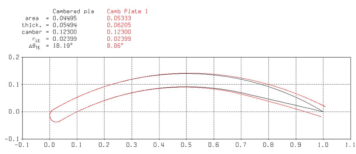
so... this isn't perfect... but I'll note that there's some evidence that if you build a "cambered plate wing", you probably shouldn't go to too much trouble to "make the back end pointy"...

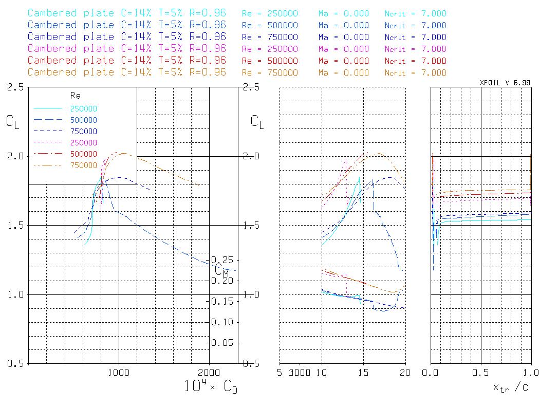
XFOIL data:

so, this is showing a gain in Clmax of pretty close to "0.2" from 1.85 to 2.05 is...
which, assuming 8ft span, 16" chord, and 60mph would mean ~20#'s of more downforce (assuming I've done my math right) for the "not pointy airfoil" wing setup... which makes some sense... it's basically a "free gurney flap" in some ways.
of course... this is theoretical, and it comes at the expense of drag... but probably not enough that it's worth "saving the labor" of not shaping the trailing edge
An airfoil won't have a pointy end per sa, the top of the surface comes down to the Bottom surface, It makes the air Speed up to catch up with the underside because it's longer and air has farther to go and makes lift.
the Bottom could be flat as long as the top has the Curvature to make lift

you guys are amazing. This thread is turning into exactly what I had hoped for!
Sleepy - yes, I noticed late last night my Reynolds number error. I think when I started looking at it I ran a calculation and got between 50k and 200k, but I was probably using lower 'average' autox speeds of like 35 mph and a smaller wing. I must've been. I'm sure of it. Because it is very unlikely that I screwed anything up  . Also, that is hugely good news about the back edge. That would be one of the harder parts to build anyway (any time you get into huge angles on an edge like that it gets tricky).
SV - I - very unfortunately - didn't look closely enough at the mumpkin when I had the opportunity. Did you guys test the wing at all to get some mph/downforce data?
Stafford - this is absolutely for challenge purposes. and I am also planning a splitter to match. but wing first.
I also hatched a plan for testing this wing last night by using a rig on top of a minivan (or a jaguar) and a bathroom scale in the vehicle with a pushrod through the open sunroof.
In reply to Robbie :
get a "fishscale"... 200# capacity... even digital ones aren't that expensive
also yarn... lots and lots of yarn
RevRico said:
Clearly this entire conversation is over my head,
I don't think so at all! The point of this thread is that anyone CAN make useable aero with simple tools and materials. You don't need to be a PhD to make down force.
I ran the cambered plate you listed thru a software similar to what sleepyhead used and was going to post up the ground effect results but ran out of time this morning. It was 2D but would have shown the pressure responses and the leading edge sensitivities in pretty colors for everyone to oh-ah over. Maybe when I get home from the wind tunnel today...
Robbie,
In your testing, be prepared for the wing to "weather-vane" and try to turn into the wind (reducing angle of attack). That would be the CM 1/4 plots from the website you are using. That data will give you an idea of how much the wing wants to unload itself, if the pivot were 25% back from the leading edge. There is a neutral point for the loading you want, but you would have to work out the moments and loading point to find that location. That would give you the lightest loading on any structure used to hold the AOA. General location is around 33% chord (from the leading edge).

mke
Reader
3/27/19 9:55 a.m.
This graph and the corresponding Cd show a discontinuity at 10 degrees

Its pretty much impossible for lift to change that fast with that small a change in angle so you can be certain that there is a problem at 10 deg and anything after is is probably not real as you've crossed into a different range almost certainly governed by different equations, whence the jump.
I think the way the graph should be read is DO NOT exceed 10 deg, (probably don't exceed 9deg) without a whole lot of actual testing so you understand what is happening at 10 and if it helps or hurts...but it almost certainly hurts since you've left the standard design space.

mke said:
This graph and the corresponding Cd show a discontinuity at 10 degrees

Its pretty much impossible for lift to change that fast with that small a change in angle so you can be certain that there is a problem at 10 deg and anything after is is probably not real as you've crossed into a different range almost certainly governed by different equations, whence the jump.
I think the way the graph should be read is DO NOT exceed 10 deg, (probably don't exceed 9deg) without a whole lot of actual testing so you understand what is happening at 10 and if it helps or hurts...but it almost certainly hurts since you've left the standard design space.
This is a function of the Reynolds number discussed up thread. The local discontinuity is likely also a function of the solver used for the data, which is a very old/simplified code. there are newer more "accurate" solvers available, but for the first look at various sections it is sufficient. I can see several possible causes for the discontinuity that arise from the shape of the section, one of which would be overcome by increasing the AOA further than the area you highlighted (the curve is not terrible beyond that point, just very steep).
In reply to mke :
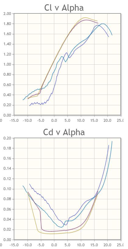
Yes, I agree, something weird happens there. That graph is however based on a flawed Reynolds number as pointed out by sleepyhead. Here is a similar comparison with the reynolds numbers I am more likely to see. The purple and yellow are the e423 and the blue are the cambered-profile. You can see now why the e423 wing is an improvement over the cambered profile.

NOT A TA said:
stafford1500 said:
I ran the cambered plate you listed thru a software similar to what sleepyhead used and was going to post up the ground effect results but ran out of time this morning. It was 2D but would have shown the pressure responses and the leading edge sensitivities in pretty colors for everyone to oh-ah over. Maybe when I get home from the wind tunnel today...
Yes please!
Agreed, it would be really interesting and valuable information. Might be worth starting a new thread so that it doesn't get lost in the search for 30" diameter pipe.
All of those graphs illustrate why I like deep wing chords
1) Your AoA and CL get to be lower for the force you want
2) The Reynolds number goes up and makes it more likely that the wing will actually work
chaparral said:
All of those graphs illustrate why I like deep wing chords
1) Your AoA and CL get to be lower for the force you want
2) The Reynolds number goes up and makes it more likely that the wing will actually work
There are a few downsides to the longer chord argument: weight goes up with size, efficiency goes down with reduced aspect ratio (length & width comparison), and finally if you have the wing running at less than best downforce, most folks will turn it up to 11 and go faster through increased downforce (assuming you balance it properly front to rear).
Overall though if you do not have a ruleset to work with, bigger is better for "easier" downforce.
Where can I get Challenge-friendly blue foam as shown up thread?


