Nice knob match from Mouser. Yes, knob matching is a "thing" so you are not alone in the quest for symmetry. Looking forward to the next phase.
Nice knob match from Mouser. Yes, knob matching is a "thing" so you are not alone in the quest for symmetry. Looking forward to the next phase.
I can see there being two very different types of personalities in the modular synth world - those that want all their modules to look exactly the same, and those that want a complete riot of different looking components, like a bunch of boutique guitar effects pedals.
In this case, the goal is for a small integrated unit so trying to make it look like it's all from the same source seems correct. The knob match isn't perfect but it's close enough, especially since Behringer used at least three different styles of knobs on the synth and I'm pretty sure there were occasions where Moog just used whatever was easily available that day!
Related automotive story - the vintage Land Rover community, back when I was involved in it, was trying to determine what the "correct" color for the engine block was. The answer appears to be "whatever leftover paint was sitting around".
Funny you should mention that...
I worked with a UK colleague a few years back who was involved with Land Rover at the point where everything had gone south badly. As it was explained to me, there were thousands of vehicles in various states of build which were pulled off the line for any number of reasons at the final check point. These vehicles were simply left for dead until it was finally recognized something needed to be done. First order of business was to figure out what was causing the huge quality control issues. Apparently, the workers were not empowered to stop the line if things got out of sorts. So, if one issue popped up, it had a cascading effect and then everything got out of sync and no one was paying attention at the management level because production was more important than quality. So long as the vehicles were rolling off the line, management was happy. So, many vehicles had dozens of mismatched parts or multiple unintended color schemes. It was truly a nightmare. It took quite a bit of time to get management to understand the problem and even more time to get the workers empowered and believing they could stop the line when something was wrong. Next issue was how do you fix the thousands of vehicles which were unfit for sale? Standard triage techniques were used to address the easy ones first and over time, the more difficult cases were addressed until you got to the "impossible or way too expensive to fix" vehicles which I believe were scrapped in some cases.
So, your assessment is correct. The engine color could have very well been the result of what ever was available at the time because none of that was monitored back in the day.
Who would have thought I would have info on both Land Rovers and synthesizers... And yes, I did live in Colorado for a while but not in your neck of the woods...
Interesting! What era are you talking about specifically? I know that my 1967 looks like it may very well have been a 1966 that just got given a different model year at the time of sale, it's got some specifications that are a bit off.
To be honest, I don't remember the year but given his age, I'd say it was a bit after that. It's important to remember that tis issue didn't happen over night so there's not telling how far back the issues go. Mid 70's would be my best guess. He is nearly impossible to contact otherwise I'd reach out to him. Haven't heard from him in years.
Or the US for that matter. Vega, Pinto, and V-8's that produce less than 200hp. It was a very sad time. Yet here we are, 45-50 years later and some of the vehicles from that era are hot sellers and even harder to find in any kind of reasonable condition. To each their own...
Well, that was back when the labour relations in the British motor industry where so good that workers would leave their lunch leftovers in car's heater ducts as they'd put them together.
Parts are here! First, the skiff. Which is a goofy name and useless when talking to anyone who's not into Eurorack, so I'm just going to call it a console from now on.
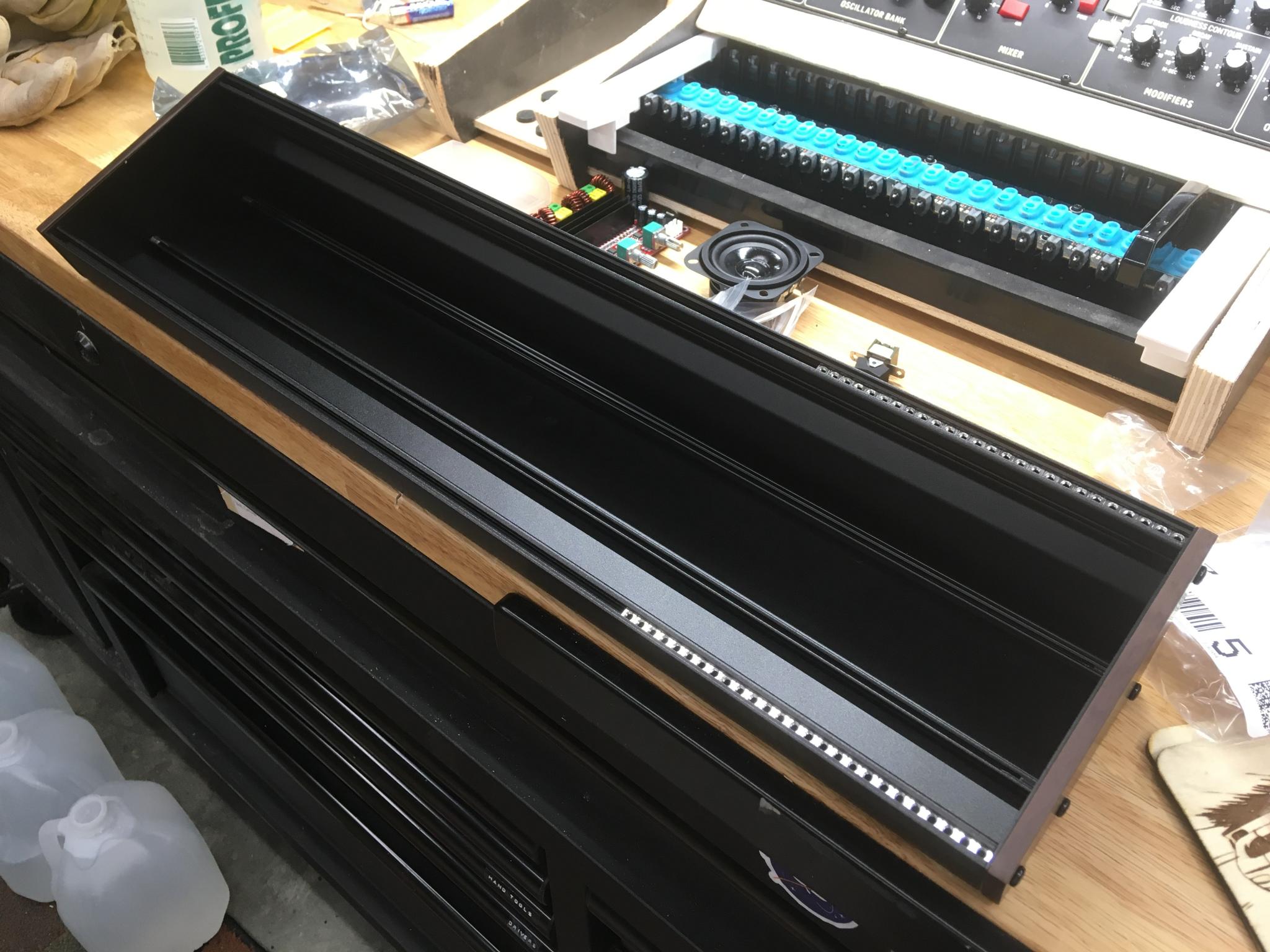
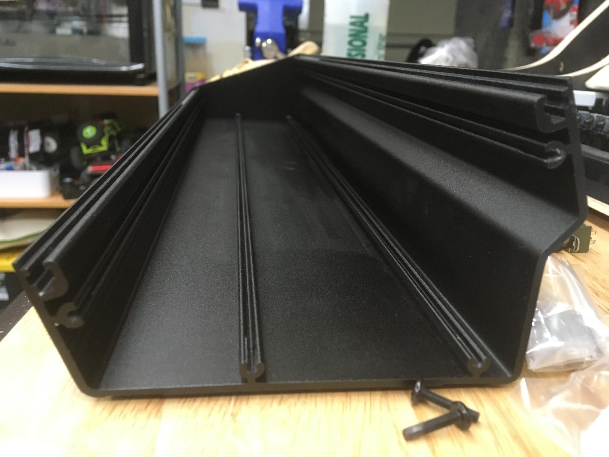
It's a simple extrusion. The lower rail is there for the mounting screws for the end caps, but it may be a good place to mount a circuit board to support switches etc. I could also flip it over which opens up some interesting possibilities.
The Q49 keyboard arrived as well, and it unfortunately was damaged in shipment. Basically, the entire front half of the case had broken mounts on it. The pitch/mod wheels were also loose on their axles and feel pretty awful. The eBay seller refunded me the purchase price - and as it turns out, none of the damage is going to prevent me from using this thing in the manner I had planned. So that's sorta a win, especially if the seller had shipping insurance.
It's interesting looking at the design of this keyboard and its smaller brother. The basic controller looks to be the same, just with a missing connector on the 25-key Q25 marked "low". Now I have to decide if I want the top three octaves or the lower three octaves. What will probably make the decision is how the alternate key functions work out. You can use the keyboard to enter data, such as the MIDI channel or a program number. On the Q49, the bottom octave does the channel and the top octave does numerics for program number - if I want to use this as a controller for other devices I'll need to have to change the channel. It would be convenient to be able to change the program (ie, swap instruments on my Roland Sound Canvas, yes I said Sound Canvas) but channel is non-optional.
Did that make any sense? It did to me.
Dropped the Model D into the new console and laid it out over the keyboard. Turns out that 104 HP is slightly more than three octaves - looks like 102 would actually be ideal. Nothing a saw can't fix. This is only going to be slightly larger than my original plan but that big span of keys makes it look much bigger. Not quite the super-cute micromoog I'd been envisioning but I'm good with it. In the picture, the right side of the synth is lined up with the edge of the top C. Man, I have got to clean up the workshop...
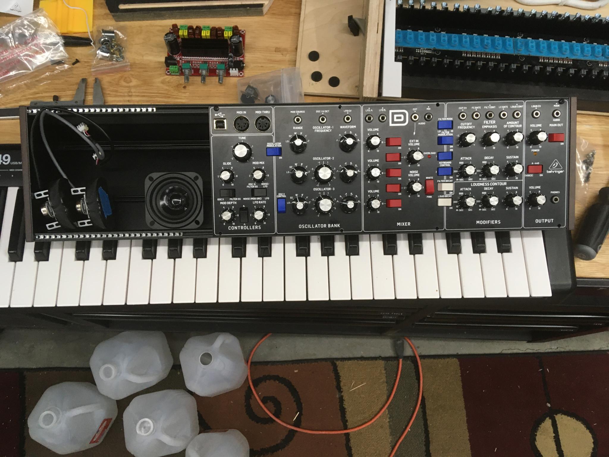
Next step is to play with control layout for my remaining console real estate and to figure out what else has to go into this case. Do I do a proper Eurorack power supply so everything is tucked away and it's all proper (expensive!), do I solder up my own (ooo, fun) or do I stash a power bar inside and just use the standard wall wart for the amp and the keyboard and anything else? Still working through all the options here. I need 580 mA for the synth and most baby power supplies seem to peak at 500.
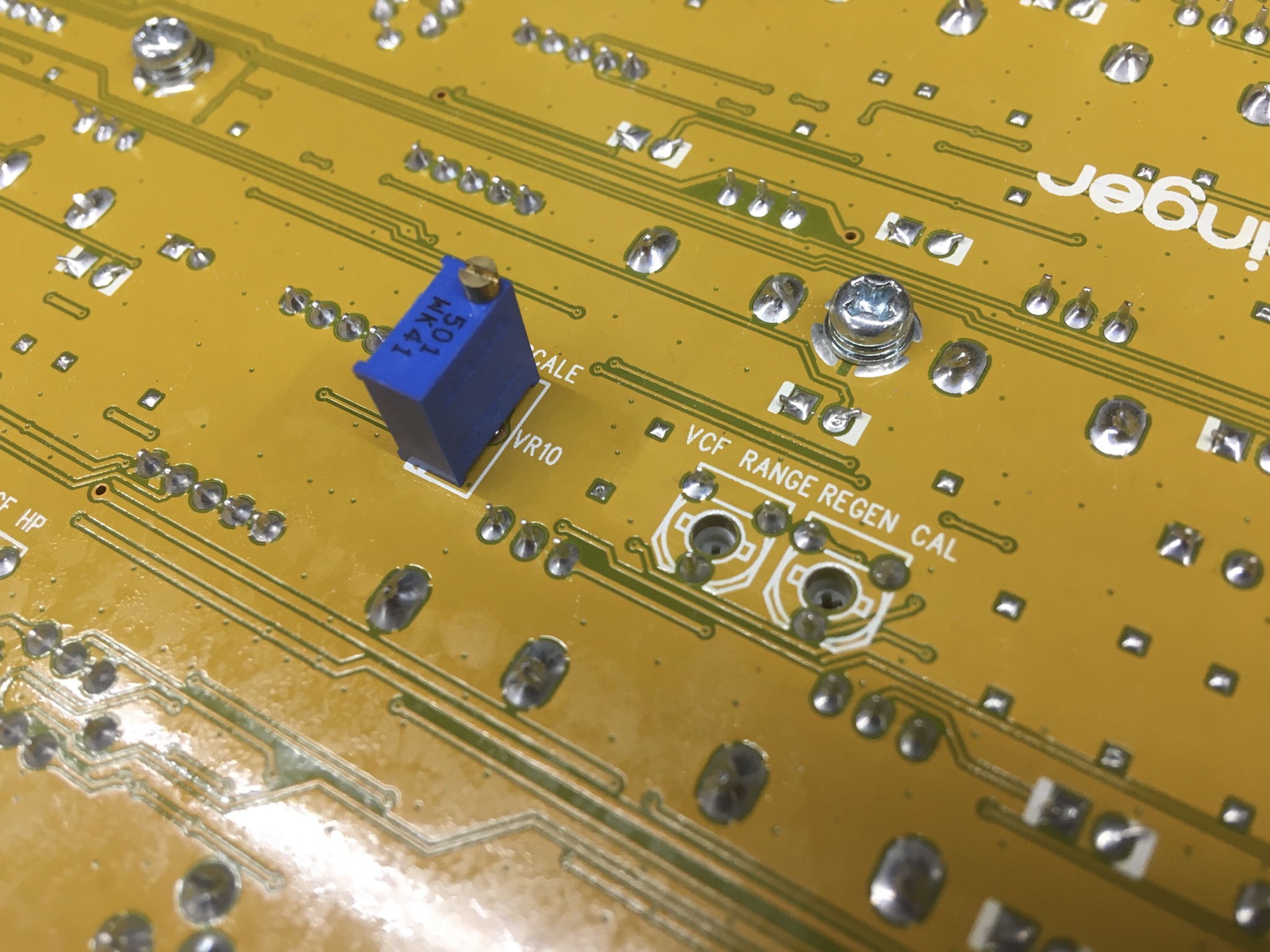
I did find this on the backside of the synth. Hidden twiddly bits! There are a bunch of them. Oooo. I also found that this circuit board is attached to standoffs that are somehow attached to the backside of the main panel so there are no visible screws on the front. I may not be able to pull off that particular trick, alas.
Keith, great thread! Nothing to add but ran down a youtube rabbit hole because of this thread and found David Hilowitz Music youtube page. Thought I would share.
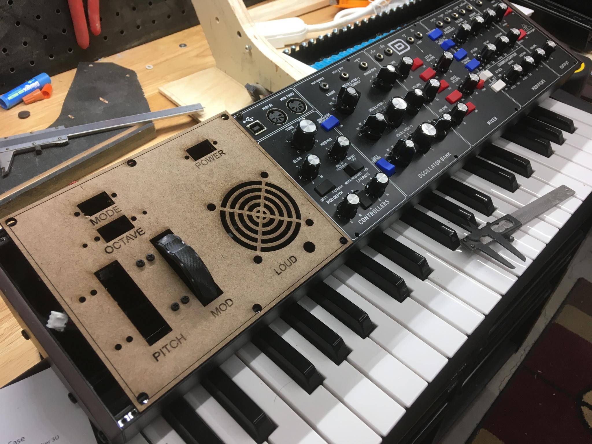
First shot at the side panel. I got some of the dimensions a bit wrong (don't trust online diagrams, kids!) and I didn't even try with the font, but it's close enough. It's 10mm (2 HP) shorter than ideal because that's how much I'll shorten the console to match the keyboard. I still haven't decided what to do about power or how I want to deal with a monitor speaker, but it's a good way to play around.
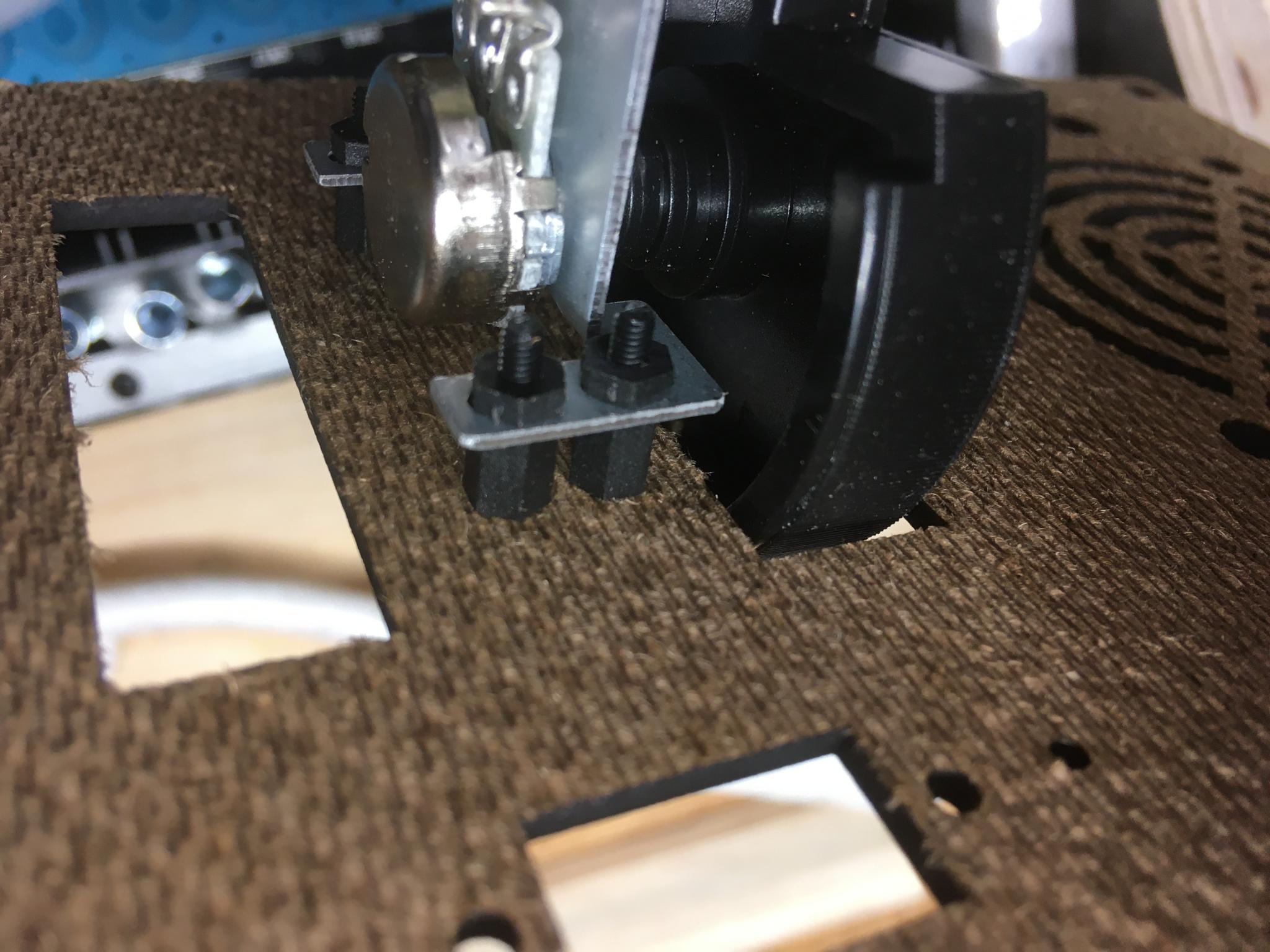
The wheel is mounted using little nylon standoffs. It means exposed screw heads, but I don't think there's a real way around that unless I buy a stud welder. No, I will not use this excuse to buy a stud welder. Although I would love to.
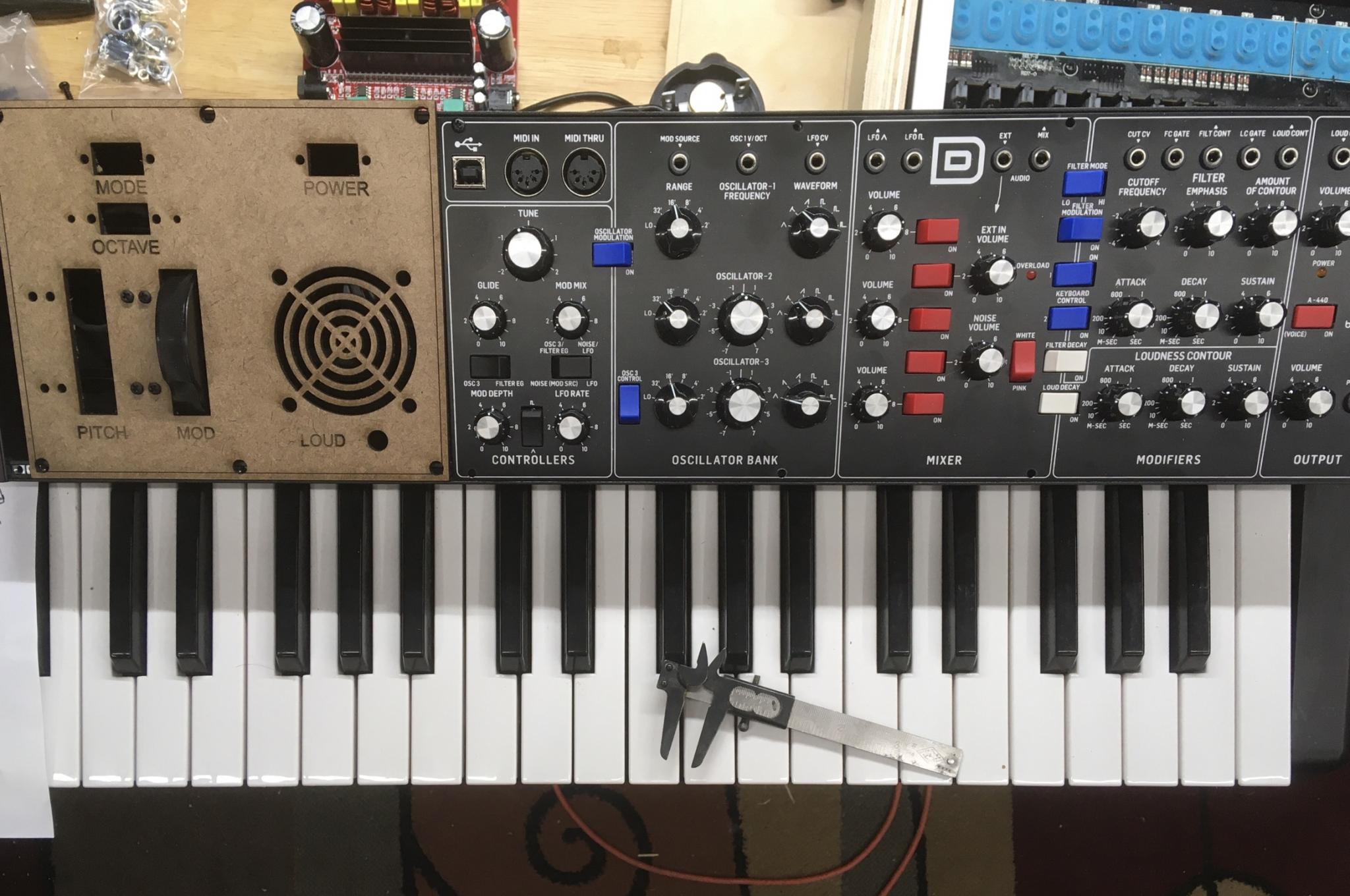
You know, I don't hate the aesthetic of having wood on the side. Would it be worse to have a painted metal panel that didn't match? Also, seriously, don't trust online dimension diagrams.
Skiff is actually an appropriate name. The normal size enclosures are most time called boats and are much deeper and not angled. Hopefully that will help with the terminology. Power supplies for Eurorack are all over the map and the debate is ongoing. I was able to power the entire 1512 with a single brick style power supply without issue. A wall wart will be more than enough but don't be shy about having a little headroom.
Yeah, the online stuff can be a bit, well you know. Take you own measurements and then verify it against multiple sources to be sure. Also, the screw holes are almost never right or the correct size but again, you now know that as well.
Add a couple HP to the overall size and then get the height back down where it needs to be and you'll have a sweet setup. If the wood look doesn't work for you, there are a couple tricks I can share when working with a standard aluminum plate setup.
I understand where the terminology comes from, but it's a pain to have to explain boats and small boats and skiffs to someone who is not fluent in Eurorack when you're just trying to talk about why there are loose keys all over your workbench :)
I pulled the Q49 apart this morning and it's not going to easily lose an octave. I'll have to saw a circuit board in half which also means I'm going to have to figure out how the heck the keys are triggered. 20 keys on one board, 29 on the other, each board with a 16 pin connector. But there's no logic I can find on the board other than a rack of diodes. So how does the key signal get transmitted? I need to know this so I can tell where/how/if I can chop one of these boards. I'll spend some time prodding with a multimeter.
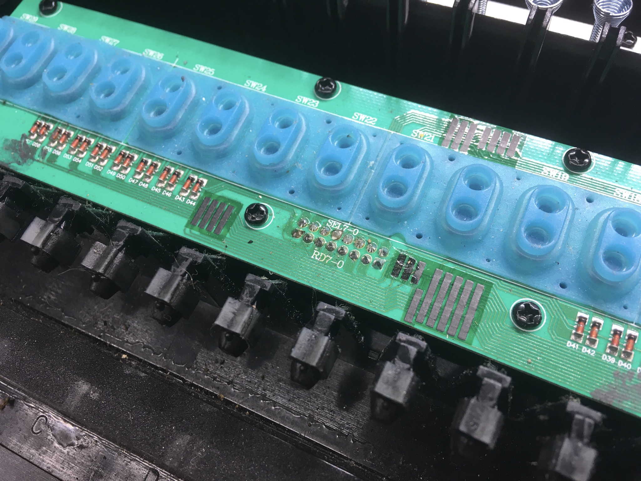
If I can't figure out how to shorten the keyboard, I may have to go back to the original design with the wheels beside the keyboard in a...dinghy? Kayak? Raft? Outrigger? I have some ideas there.
For power, I need 580 mA on the 12v bus for the synth. It comes with a 1000 mA wall wart. The keyboard can run off the USB bus which means a small amount of 5v power, or it has a 9v wall wart. Most hobby sized power suppies for Eurorack seem to peak at 500 mA 12v and then you have to get serious. I also have a monitor speaker I want to add if possible that will pull up to 80 mA on the 12v bus. So I could use the synth wall wart, split off a bit of juice for the monitor and then find a way to knock that down to either 5v or 9v for the keyboard. This will be less universal Eurorack than using a proper power supply, but that may be acceptable.
Good news! When the synth is powered up with the wall wart, there's 12v on the Eurorack connector. So I can piggyback the monitor easily. Now I just need to come up with a 5v or 12v option.
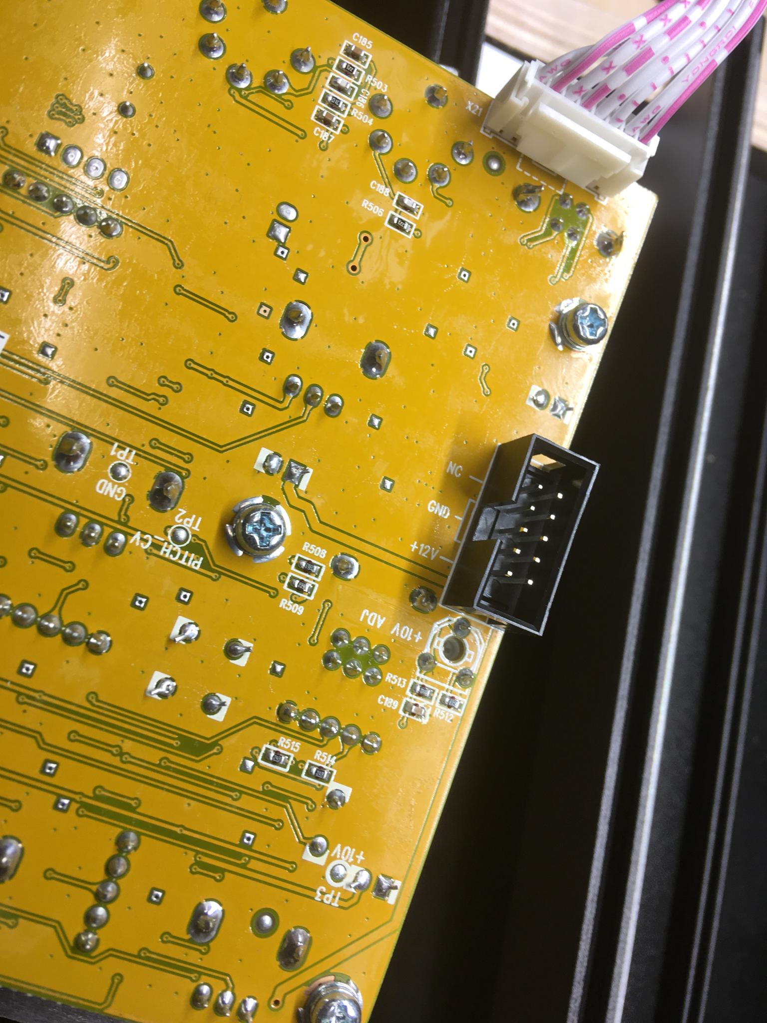
As for the keyboard, I am now learning about multiplexing switches :) This keyboard is velocity sensitive but does not have aftertouch. Velocity sensitivity comes from a pair of switches on each key that are offset in the travel - the faster you hit the key, the less lag time there is between the two switches engaging. Anyhow, cutting this thing down should be possible but I'll want to make sure I have it figured out before I start to chop. If I cut off the lower octave, I'll have to slice between SW8 and SW9 -right through the output connector. Again, the upper octave is looking more and more like the right choice.
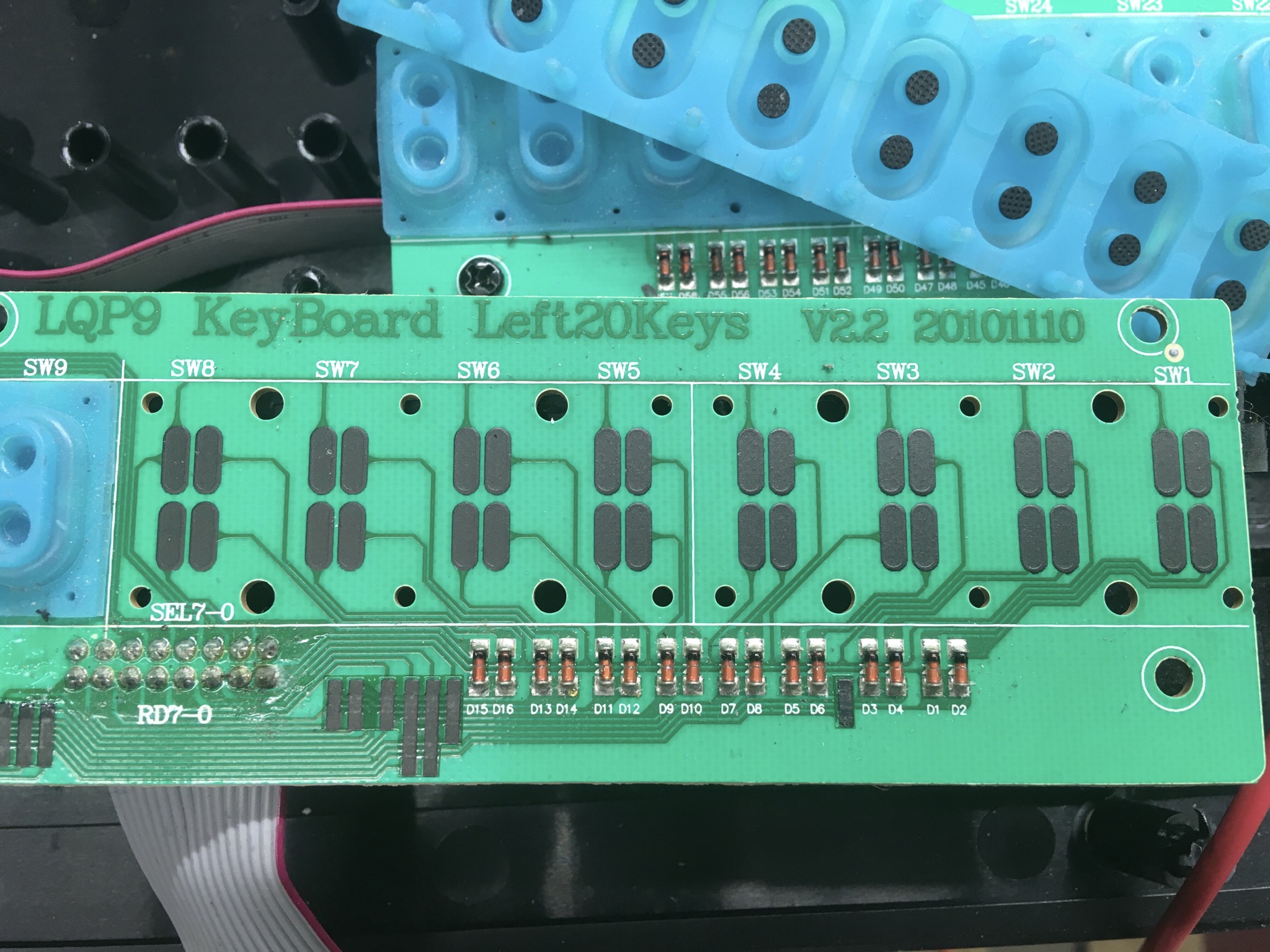
Here's where the cut would happen if I chopped the top octave off the keyboard - basically, right through SW12, which would be discarded. I'd have to add two wires and diodes for SW13 (the top C) but that should be it if I understand this correctly. The loss of the circuits for the upper keys won't matter, it'll just be like they're never depressed. I'll take a closer look at the traces and make sure there are no shared traced that need to feed the lower 17 keys but we may have a way forward.
I can octave shift multiple times using a separate switch on the keyboard so it doesn't really matter what octave I lose. Also, note the broken case post at the top of the picture - this poor keyboard is perfectly suited to my plans.
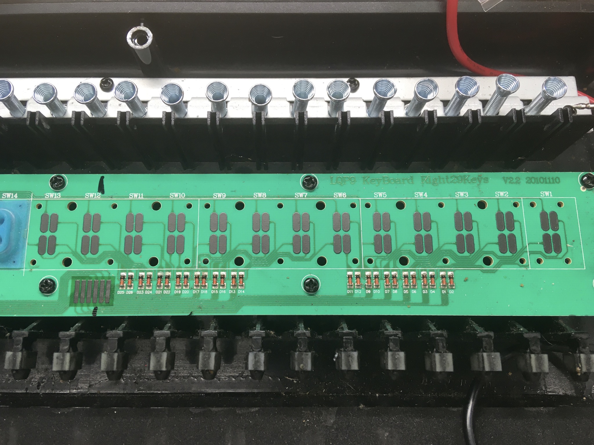
IIRC, the Eurorack power supply boards used for providing power to the individual modules has the ability to take in 12v from the wall wart/brick and then separate it in to 12v+, 12- and 5v. Might be worth looking into.
I looked at the Eurorack options. They either can't supply enough power on the 12v leg to feed the synth or they're highly overpowered for my needs with an associated size and cost penalty. Size is a bigger problem here.
It's pretty easy to get 5v out of 12v using a 7805 regulator and a couple of caps. That can be done for about a dollar. I decided to spend big money and pick up this $10 voltage regulator along with a USB socket to solder into it. I'll feed it 12v and then run 5v into the keyboard via USB. Alternately, if that plan doesn't work out, I may just bung a 9v battery into the case to power the keyboard. I realized a couple of days ago that my Roland keyboard runs off batteries and I have no idea how long it's been since I changed them. Like, what year.
Spent some time tracing and beeping and I deciphered the multiplexing. 8 wires in, 8 out which means 64 possible combinations. Each note needs two switches which means we can have up to 32. And this daughter board has 29. Convenient, although a bit of an odd cutoff.
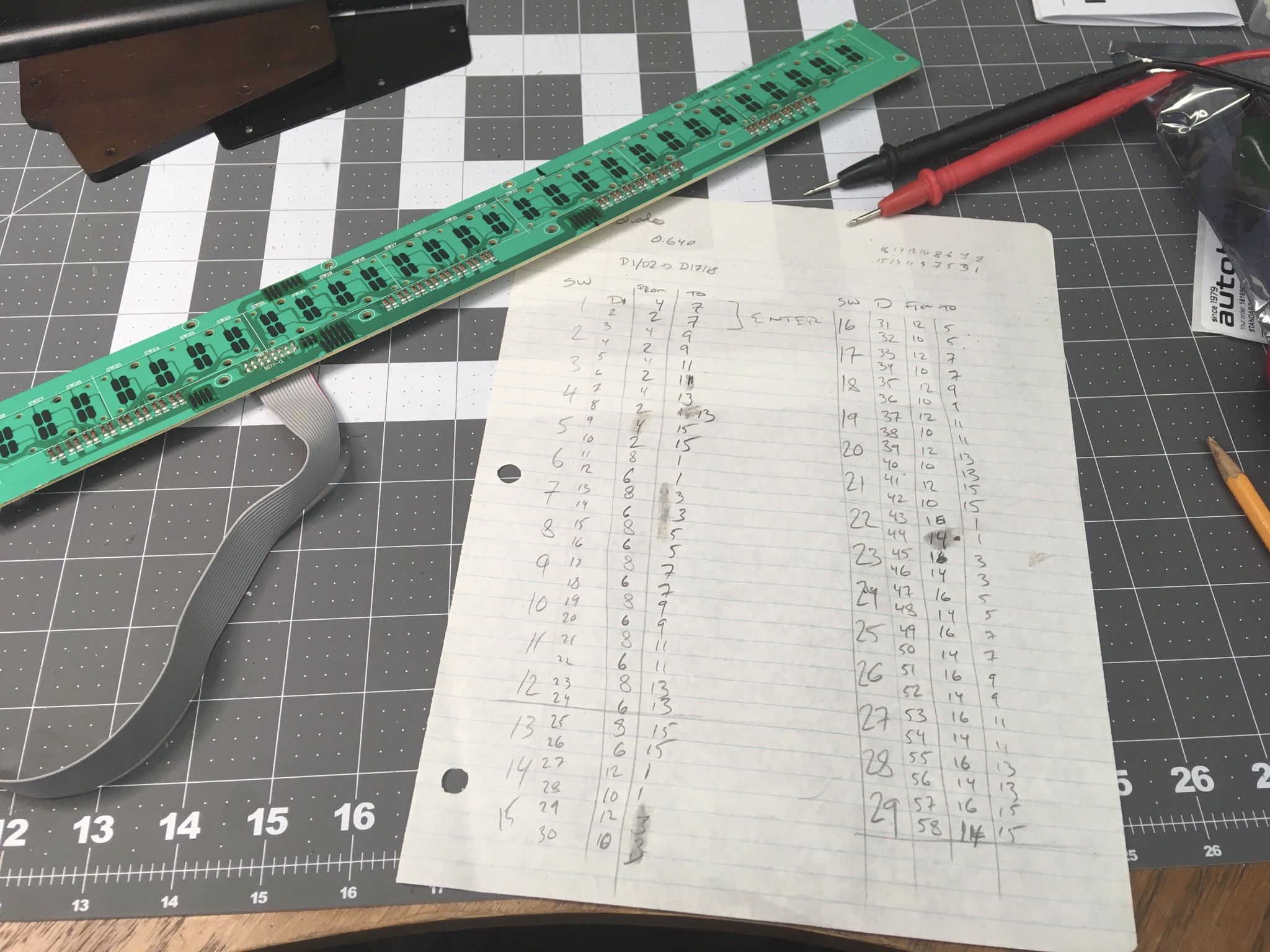
As it turns out, amputating the top 13 keys would have been painless. But I wanted that last C, so I had to patch it in. Scraped the traces clean and soldered in a couple of diodes, then ran that back to the correct pin.
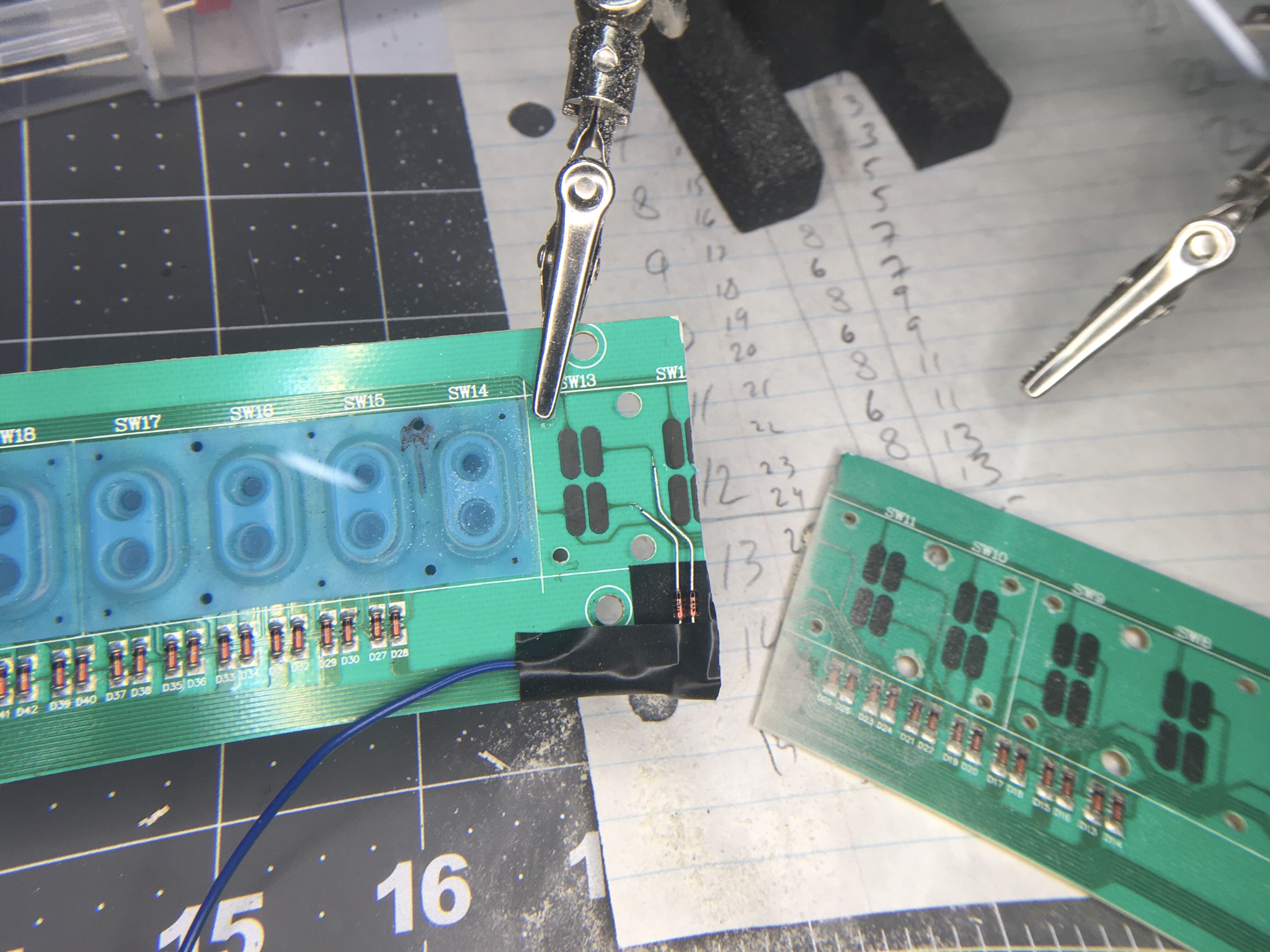
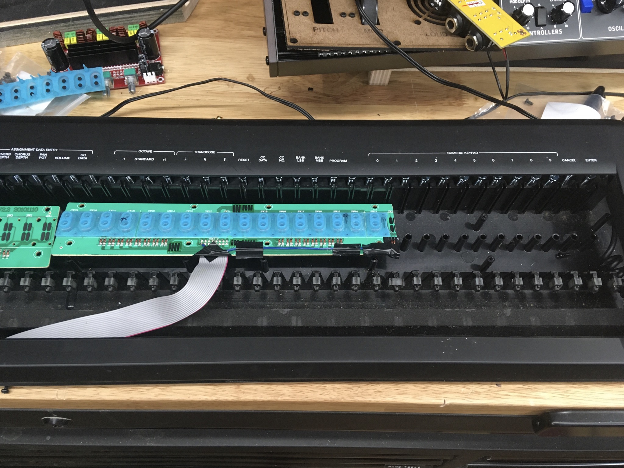
The tape is temporary, I'll hot glue it all down later. A quick test indicates the patient survived the amputation and I have three octaves of bloop. So now it's just the mechanical aspect of the keyboard modification.
Progress! I was able to get some time to work on this today (it's apparently a holiday of some sort) and it's made some big steps.
I cut the 104 HP skiff down to 20.5" to better match the width of the keyboard. That makes it a 102.5 HP skiff. No pics, but I just scribed it and used a hacksaw to cut it down.
Came up with a way to mount the skiff to the end caps. Makes assembly order a factor, but it works.
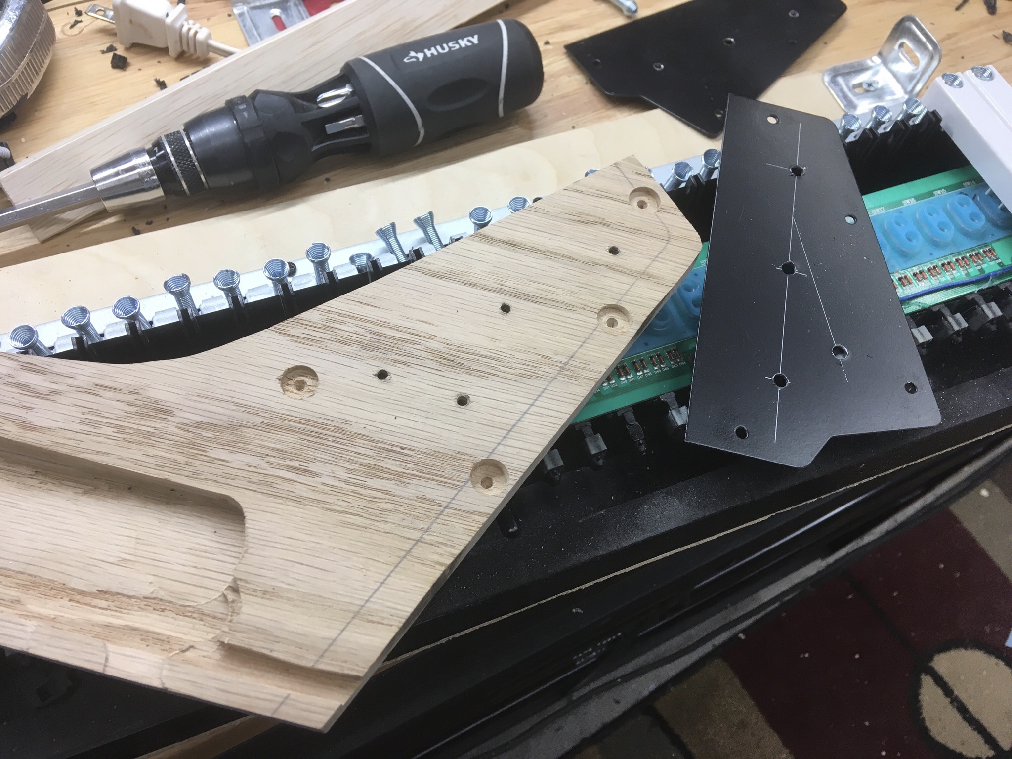
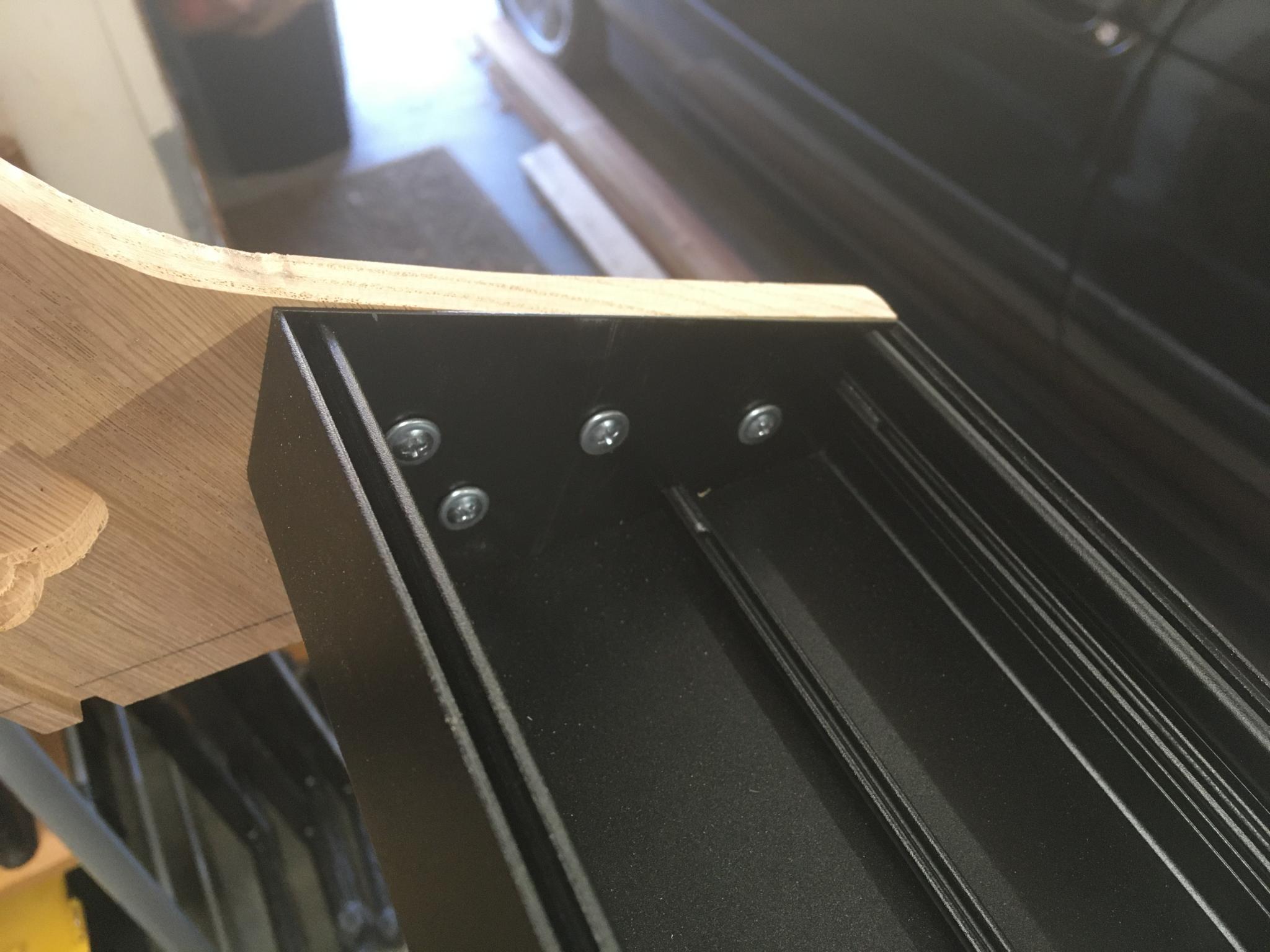
I did put the skiff in upside down compared to how it's intended to go. It has a much nicer side profile that way.
Partially assembled, it's starting to look real! I still have to do the remaining wooden pieces and some final location of sub-boards, but I'm liking this. The partial wooden bar above the keyboard is just for visualization, it'll be full length. There's also a lot of final sanding work waiting. But I can see how I will finish the build.
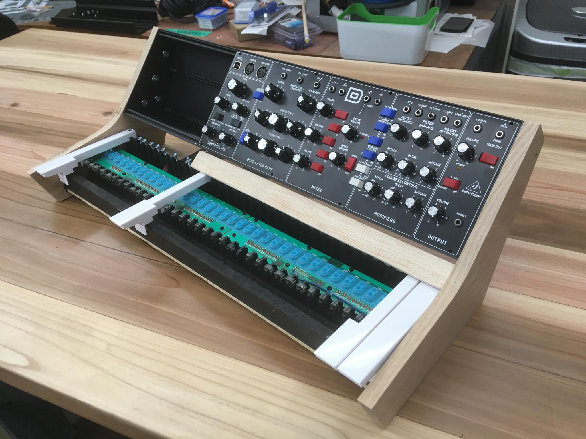
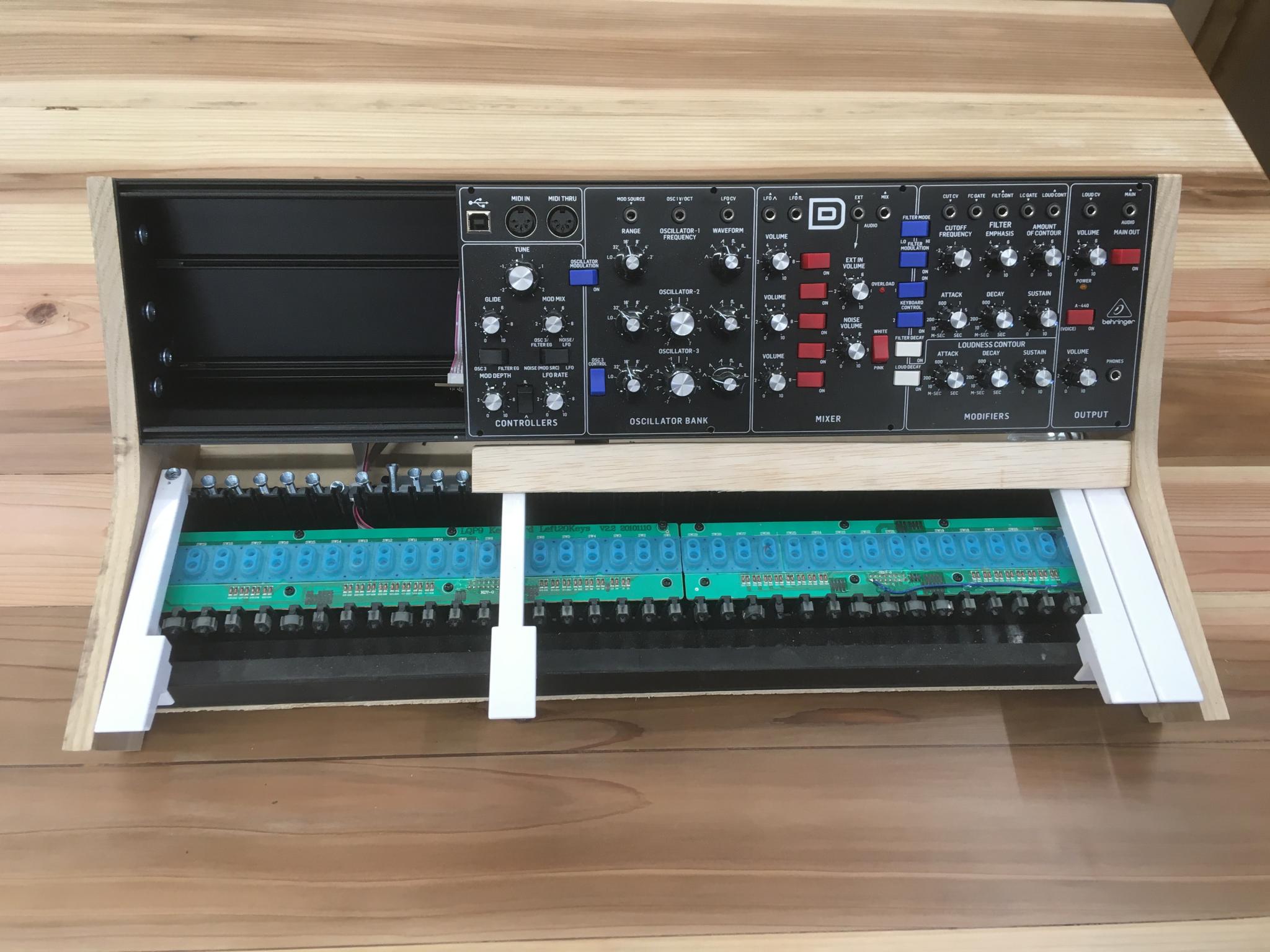
Today was productive day. I decided to build the real box.
Step 1, the two side pieces and the lower front bar. This has good structural integrity already. The cedar tabletop it's sitting on was yesterday's project and included tearing down, refreshing and sharpening two very old block planes.
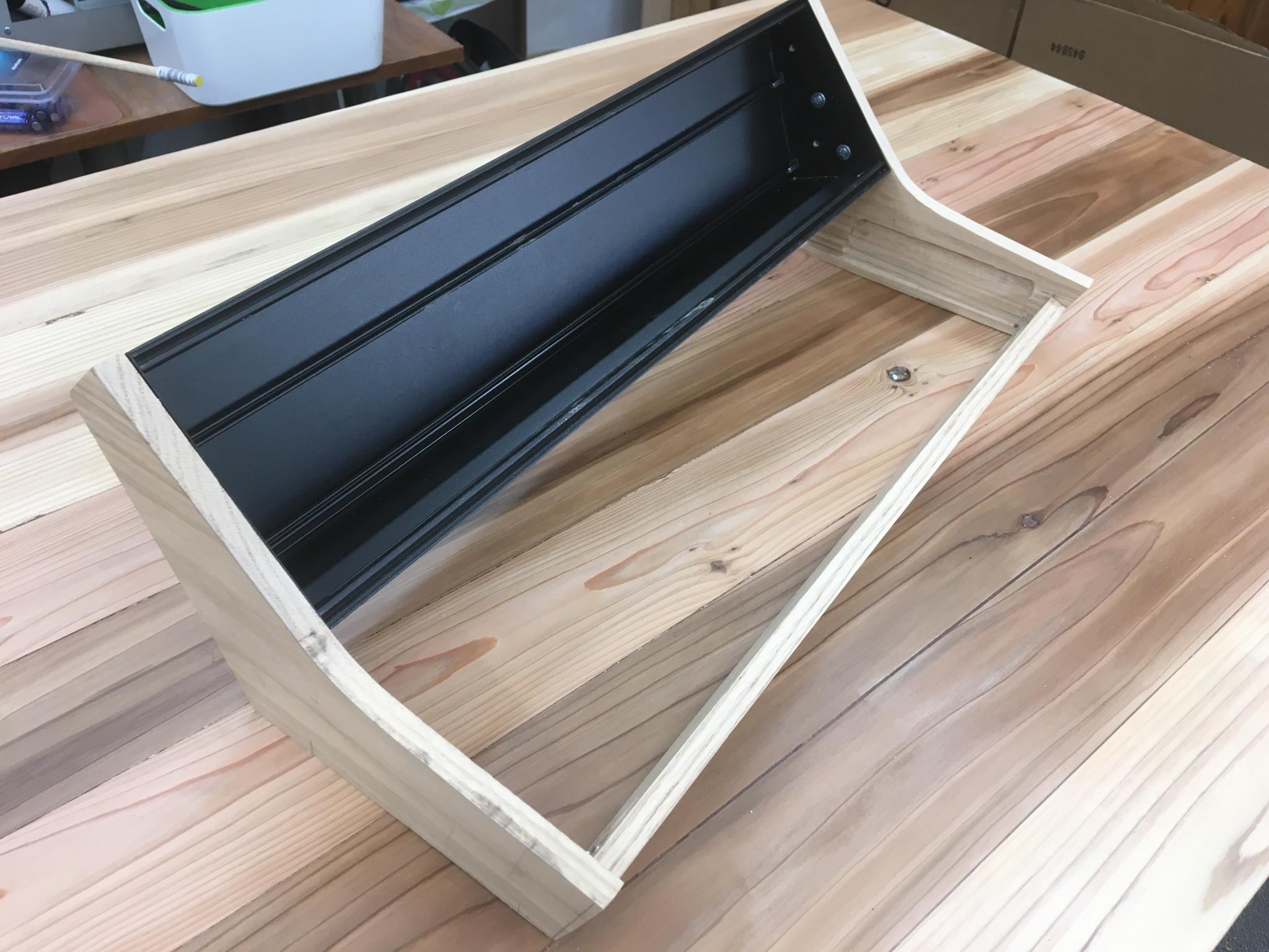
With the bottom panel and the...I'll call it the "key bar" that goes between the keyboard and the rail.
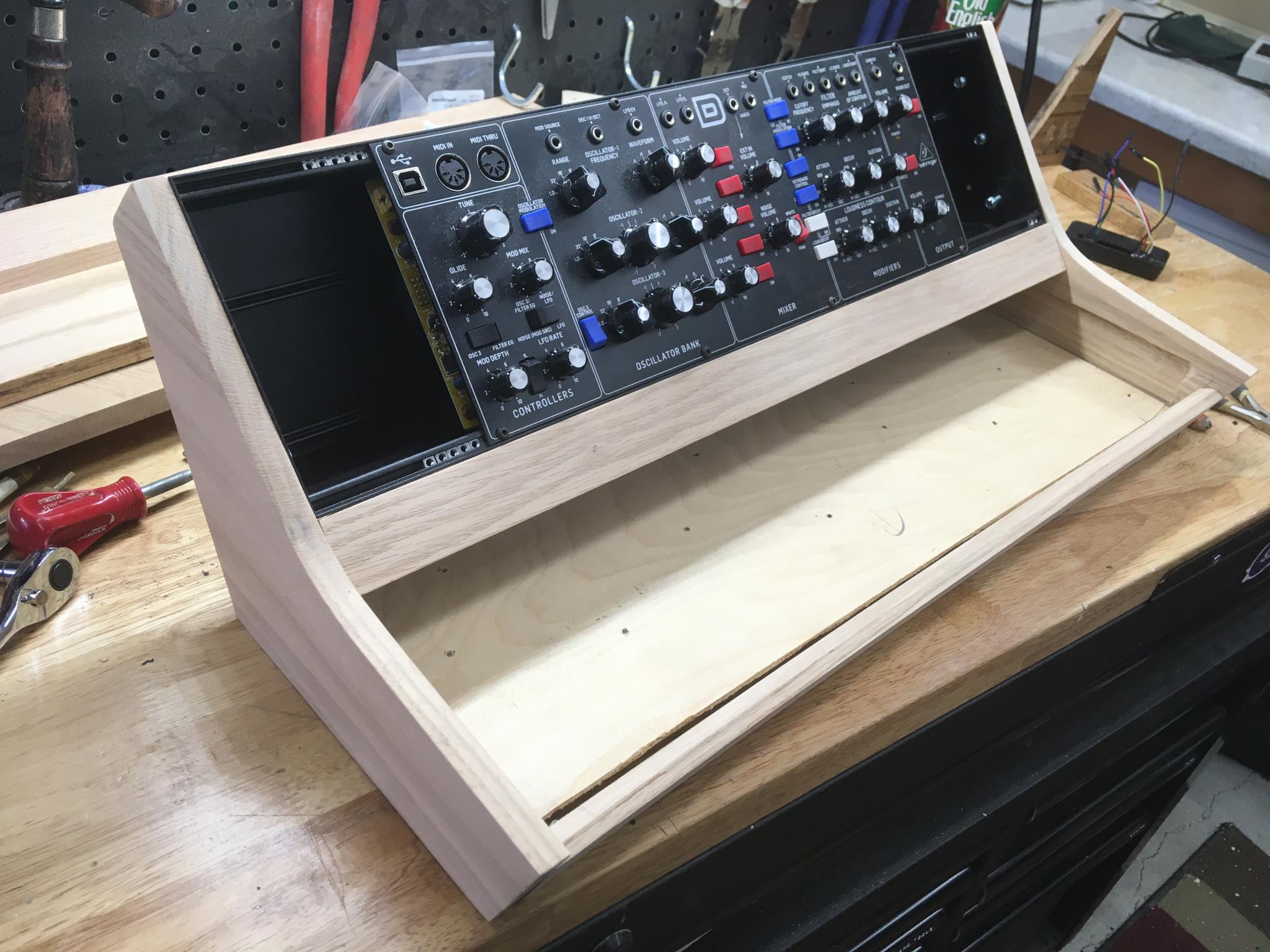
That key bar took a lot of work and fine tuning to get the clearance to the keys tight and even. I love my router table.
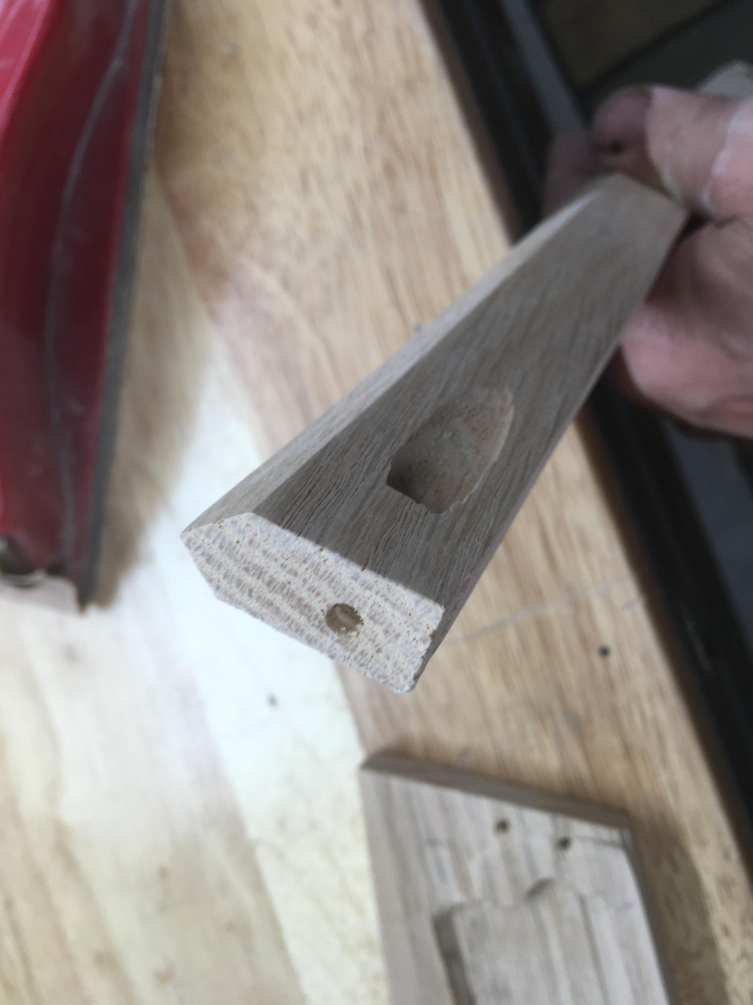
I've been able to build it without visible fasteners, which is a big win for a barely-novice woodworker like me. But this also means that assembly order is critical. For example, these pocket screws are the last item.
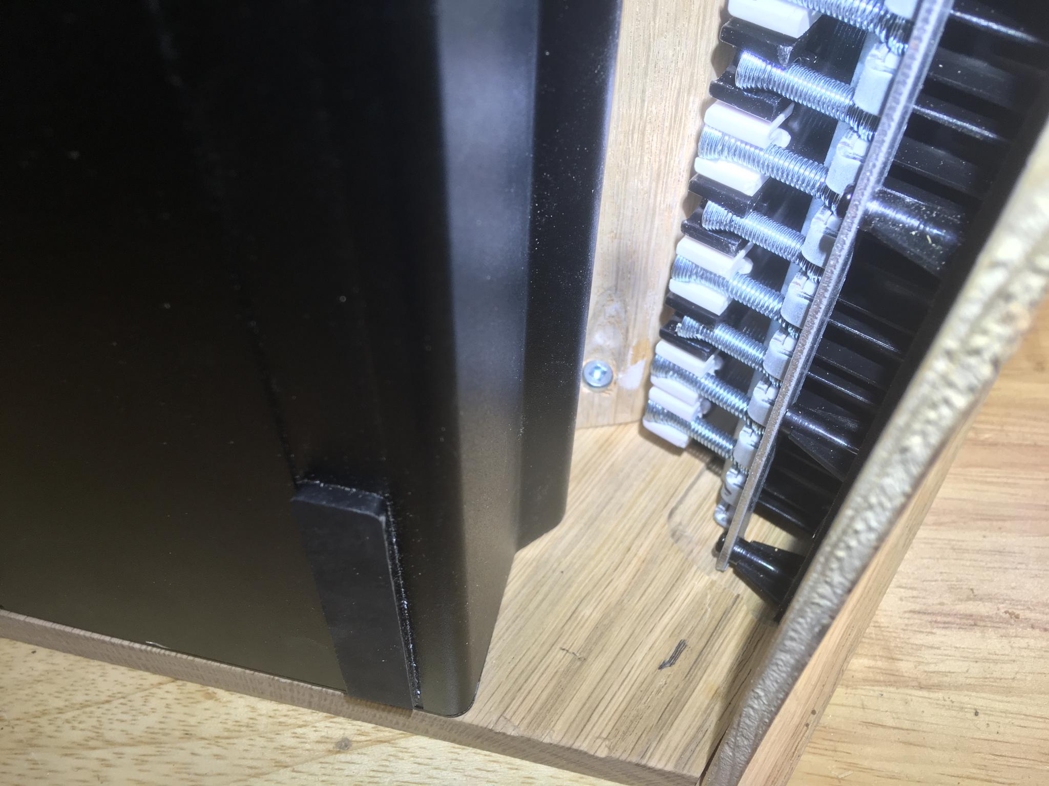
Half of the white keys are installed after the keyboard panel goes in but before the key bar.
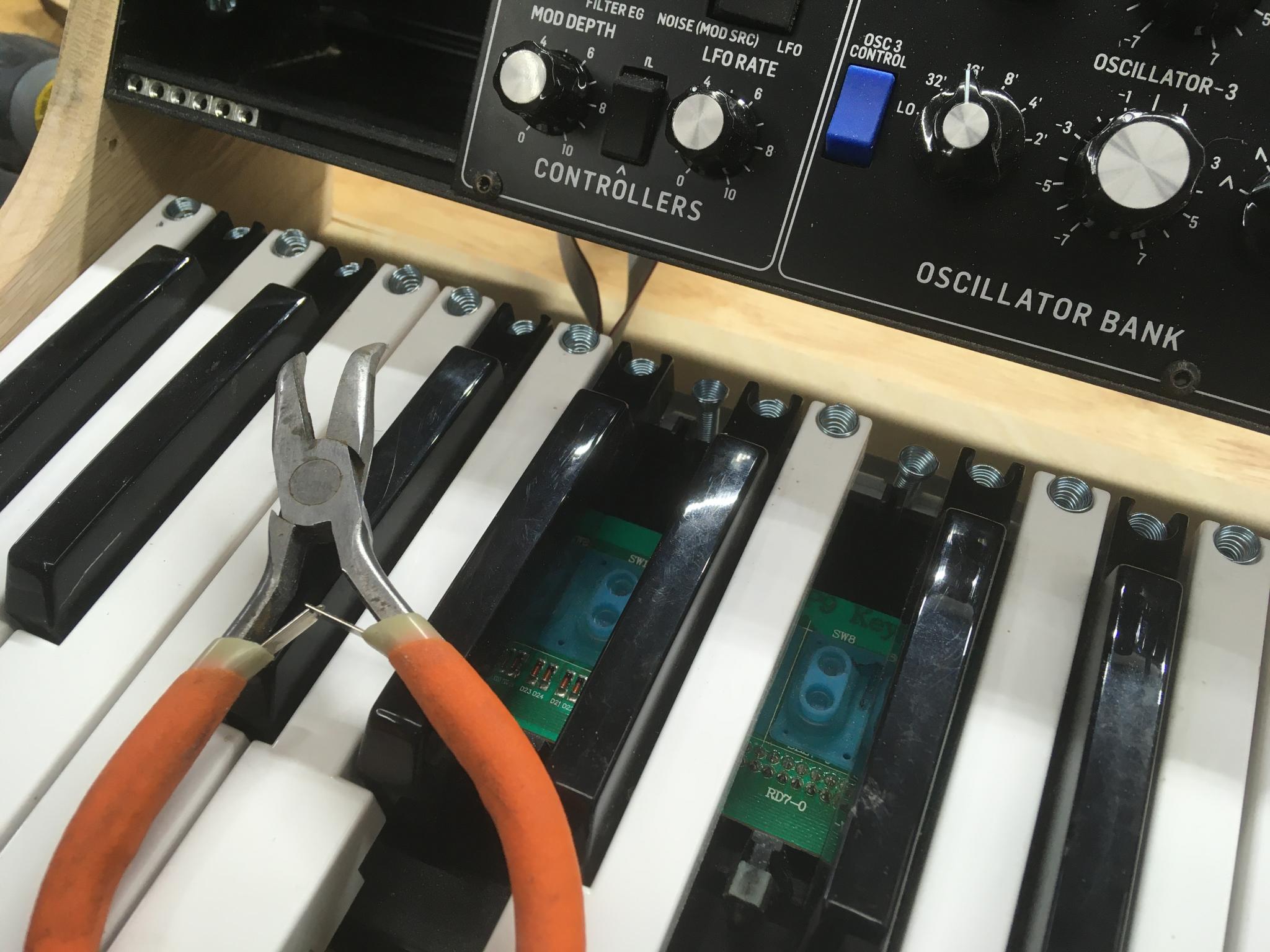
I changed to hex head screws to attach the bar to the side panels so I can use a ratchet on them - better access than with screw heads.
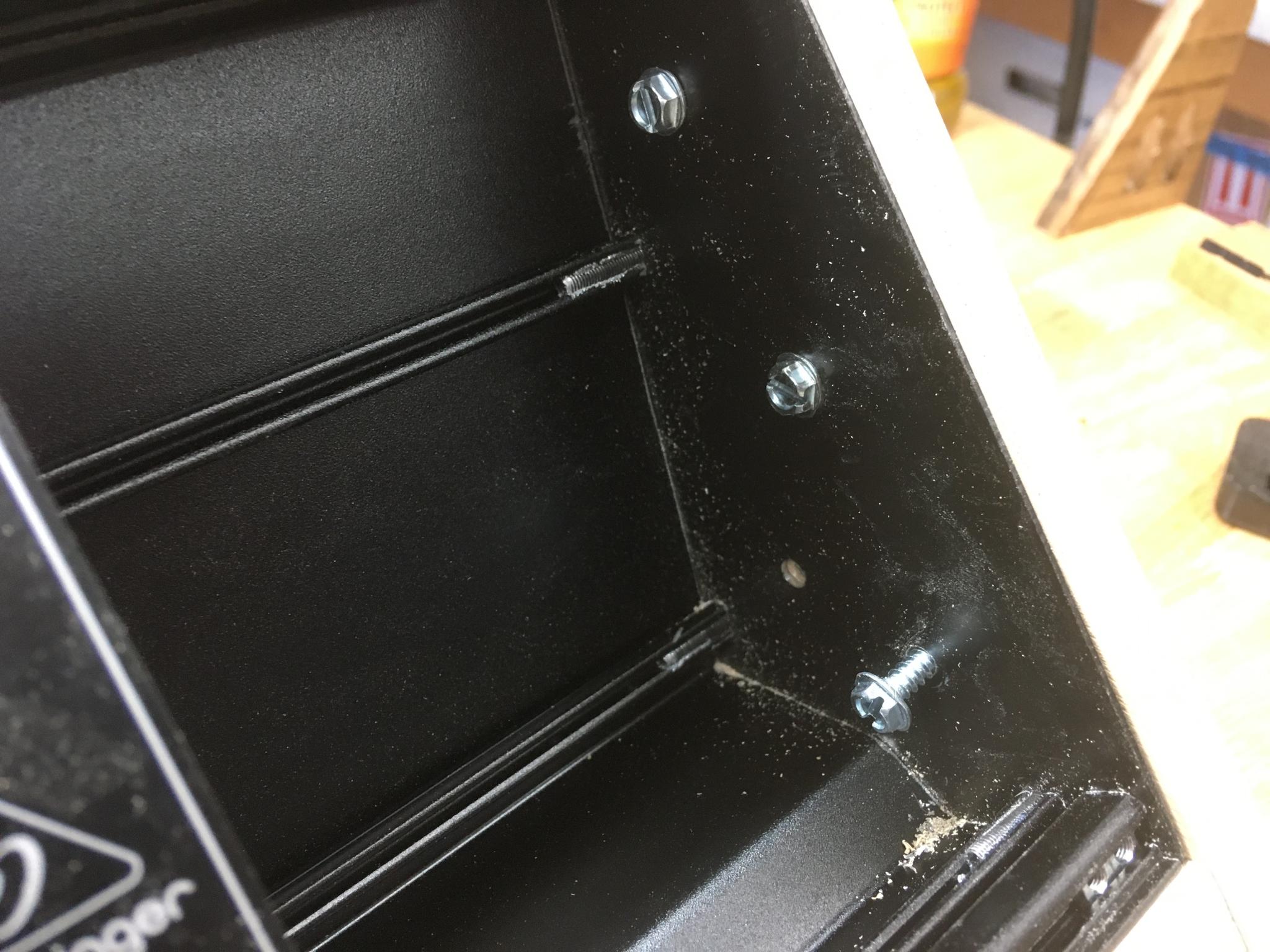
Final test assembly before finishing the wood. There are still a lot of packaging problems to solve with the electronics but I'm waiting for some parts and have to fix the laser. But I powered it up and performed a test. We have bloop! And as a good sign, I spent a fair bit of time noodling just because.
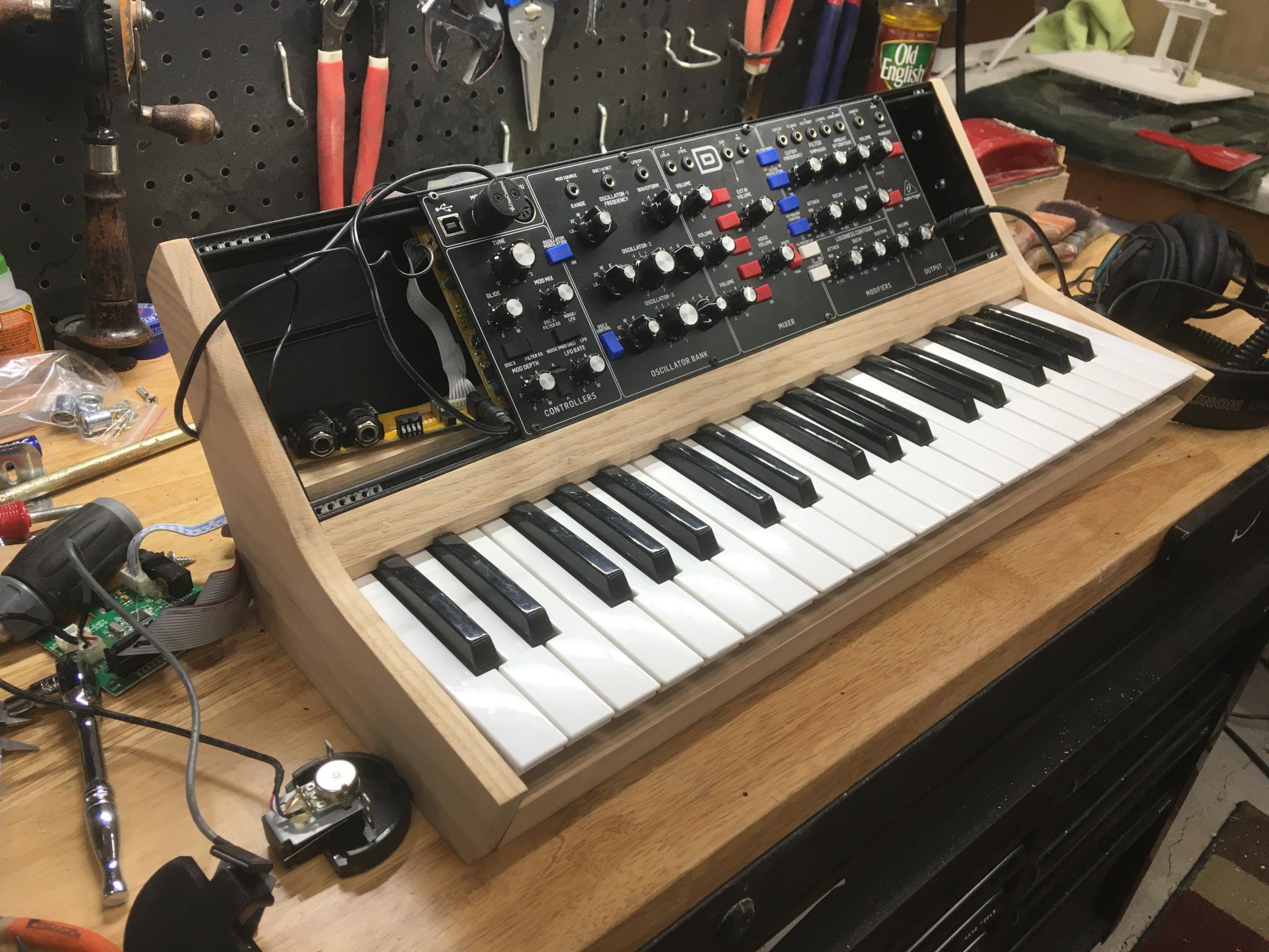
Now it's disassembled again for final sanding and so I can wreck that beautiful wood with ham-fisted stain work. Sigh.
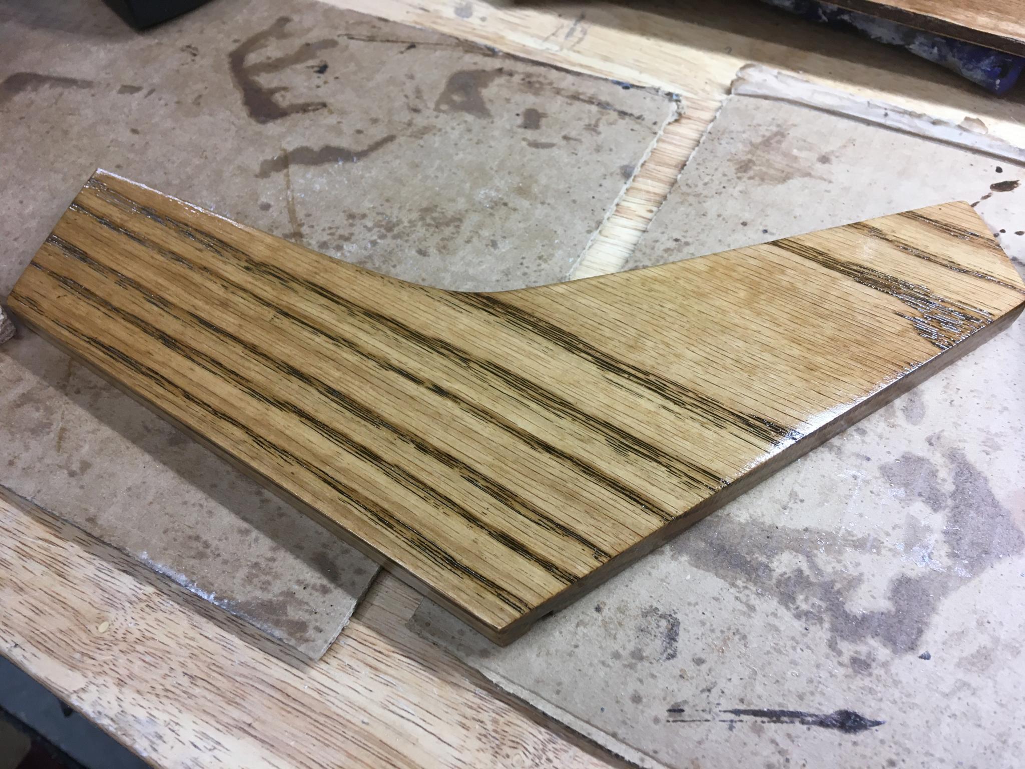
Have I mentioned that I am, at best, highly mediocre at woodwork? I started by finishing the oak using a combination stain/poly concoction that I used on the Majestic radio fairly successfully. The test piece looked good. But the actual pieces looked very different, and terrible. I might have well have made the bloody thing out of MDF. That can got put back on the shelf and will probably stay there forever.
I sanded everything clean again and started over. First, a wipe-off stain I've used on all sorts of things because it brings out the grain nicely. Then I decided to shellac for a top layer. Frenchy talks it up, I had a can of clear so I figured what the heck. Bug goo melted in alcohol.
It is my new favorite finish. Smells nice, easy to use, easy to clean up, quick drying - and it looks good. I kinda wish I'd used it on the Majestic now but I found out about it too late.
The LED light on this piece doesn't do it much justice, but it looks and feels nice. I had a can of amber as well that gave it a real golden glow, but I wanted this a little more brown. Doing the inner faces today.
Next step is to get the new panels laid out and designed. I'll post a mockup soon. The biggest decision I had to make was whether to leave the programming interface in the keyboard - you can use it to change MIDI channels, transpose or do data entry. The latter is no longer possible because it uses the top octave and someone cut that off :) But being able to switch channels would be useful, as there's a MIDI THRU jack on the face of the synth. This means I probably should put a legend on the key bar. Easy enough with the laser engraver and some care, although I will have to check to see if I was premature with the shellac in that case. The harder part will be the fact that "Enter" was the top C in the keyboard and again that has been vandalized. No worries, I know what pins need to be connected so I'll just have to do a little more wiring.
Exciting times!
Here's the current draft of the layout up top. I'll use short patch cords to jump the MIDI cables and to run audio into the monitor module, in celebration of modular synths. The synth also has a low level (to go into an amp, I assume) and a high level output on the back, both with 1/4" connectors. I may not bother with those as there's a pair of high level outs on the face of it.
If you're obsessed with everything lining up perfectly, I'll get that done :) Same with the rectangles with radiused edges. This is more of a sketch that lets me move things around.

You'll need to log in to post.