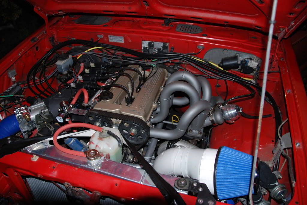
Robbie said:
Maybe a silly question. Why can't we just take something super ubiquitous, like say a Toyota Camry ecu, and load the free ems software on to it?
Embedded code only runs on the platform(s) for which it's designed. In the unlikely event that you found a piece of hardware that could run FreeEMS at all, there's a high probability that the CPU would be configured incorrectly and the pinouts would be wrong, and the input or output circuitry for the pins would be wrong, etc. So no, FreeEMS firmware only runs on hardware specifically designed for FreeEMS use, and no other hardware. Hopefully this answers alfadriver's computer question too. I think the confusion may have stemmed from this post:
FE3tMX5 said:
FreeEMS is the software/firmware that runs on the hardware you buy/build. There's a hardware section on the DIYEFI forum specific to FreeEMS, but I'm sure Fred will revisit this thread. He's on his way to CA now, then back home to NZ.
Good post, but let me clarify: The intent was always to have a well designed firmware with a good architecture at the core of the project. Around that was supposed to be many hardware designs and many diverse pieces of software to interact with the firmware. On the hardware front, for example, you might want something 4-cylinder specific to minimise cost, weight, size, complexity. Or you might want something more fully built out with dual drive by wire, a stack of IO, and enough injector/ignition drivers for a V12 with dual fuel rails. Or something smaller and simpler for a single cylinder lawnmower. Or anything in between, such as PNP solutions for various cars. Off the top of my head I can think of at least 6 distinct designs from 4 distinct designers, but only one is currently available commercially. Software wise there's been at least 4 different tuners, 3 different log viewers, and 4 different firmware loaders. All of various up-to-date-ness and quality levels. Some good. Some broken/old. I'd say my vision has been somewhat fulfilled by reality at this point. What's needed is to up the quality of each part of the package and *then* promote it more widely. I posted here because the aim of the game here is CHEAP and it's hard to beat for that purpose :-)
alfadriver said:
What I'm pointing out his how OEM's solve those problems. I've been dealing with WB sensors, and cracking them for over 10 years.
Sounds like OEMs and I solve them the same way. I've been dealing with WB sensors and *not* cracking them for over 10 years. The second sentence, of both this paragraph, and yours, was not necessary.
alfadriver said:
The heaters are turned on based on an exhaust temp model. You may not agree with that, but millions of cars on the road demonstrates it's a pretty good way of doing it. Once they are on, WB systems control the heaters just fine- no need to turn them off. I'm sure we leave them on during a start-stop event. Again, they work in the field for over 150k miles, as required. They are not heated at full blast all the time- the temperature controller is a key element in their ability to span a wide range of a/f.
What you're trying to model, and what they're probably actually modeling, and what I'm successfully modeling, is probability of exhaust borne liquid water. That's what my simple model provides, and it works most excellently indeed on my setups. If your WB sensor was on the lower side of the exhaust tip you'd need to wait significantly longer, but that's not a realistic placement anyway. Yes, something that simple is a model. A model is anything that approximates the reality you're trying to match. If you have access to OEM models/algorithms for wideband control, I'd be interested to see them on the table, though I suppose that would be guarded private IP and not for sharing. No bother, I already know what I'm doing :-)
I'm going to have to correct you on the way it works, though. Those ECUs are not going to "turn the heater on" at all. They're turning on control to the sensor, which through its very function ramps up the heater from 0% (off) to N% (on, assuming N != 0). This might be done through simple PID control, or something more bespoke and performant. It might include ramp rate limiting to avoid thermal shock from the heater (as opposed to exhaust borne water). And it will probably output some form of status to imply that it's not ready to produce a reliable reading until the heater is within range.
And there really are sensors out there that are robust to drops. That's not a proposition, that's stuff in production. To the point that it's not going to be long before cars will be in production with the sensors running and providing feeback before the engine starts. That is going to happen.
Did you mean drops or drops? I read it as let go and fall type drop, not water droplets type drops. We weren't talking about the former, and all of the sensors have various protections to help break up and slow and stop the water from hitting the ceramic element, but if enough hits it, it's done for. There's also zero value in measuring stale exhaust gas in a pipe that has been difusing with air out through the exit point for some period of time.
Ok, so you deal with the non-ideal nature of engine breathing using VE tables. That's what I'm curious about. With fixed cams, you can also write a decent set of equations that calculate the changing breathing nature of an engine. And with the calculation, you get a "load" output that is a good representation of the actual charge amount in the cylinder- which is a better way of determining the spark timing. If you are using just MAP for spark, correcting that with the VE tables is more accurate.
No, VE tables are part of the Speed Density approach, there are multiple approaches available. VE in speed density doesn't deal with non ideal ideal gas law behaviour, it deals with, as you've now said, non-ideal head/manifold breathing behaviour by parameterising it in a useful way.
As for "better" for determining spark timing. You don't calculate spark timing, you empirically define it from others experience, or your own measurements via your ears or equipment better at listening to resonances in the cylinder than your ears. The only thing you need is a reliable way of mapping a particular desired/required/entered/specified timing value to a certain corresponding set of in-cylinder conditions. Many axis styles provide this ability just fine, depending on the state of the engine (ITBs, hot cams, single plenum, turbo, super charged, etc). MAP is good for some, TPS for others, and yes, you can stick a calculated cylinder fill value in there, too. There's something to be said for intuitive interfaces for tuners, though. If they don't understand the tables they're messing with, how can they do a good job of manipulating the values in them? Simple > optimal, sometimes.
What's hard about the computer question?
Just that it wasn't understandable at all in the original form. Your clarification helped. Robbie's question helped. And I had a "shower moment" this morning re FE3tMX5's post being potentially confusing, so I hope my clarification answers your question aptly.
As for the deep and heavy nature of the questions- sorry, but I'm a calibrator with Ford (as everyone here knows), and I'm interested in the controller. Should we start another thread, or should I just go away? Sorry that I'm not making funny banter posts, but actual technical ones.
Thanks for the introduction! :-D It doesn't change anything. Once again, I know what I'm doing :-) You can do as you please, but a couple of things:
- You're dominating the thread with strange tech bi-logues, others may want to get 2c in.
- I've not had a chance to upload the rest of my media yet, and it's going to end up on page 30 at this rate, lol.
- As of next week I'll have a lot less time to reply over here, and will spend my time as I see max benefit from it, as such I may ignore posts that are trying to split hairs on the likes of control algorithms and wideband water resistance (like a fake casio watch).
Gasp. Hopefully this post goes through OK! Copy before submit, fingers crossed.


