In reply to bentwrench:
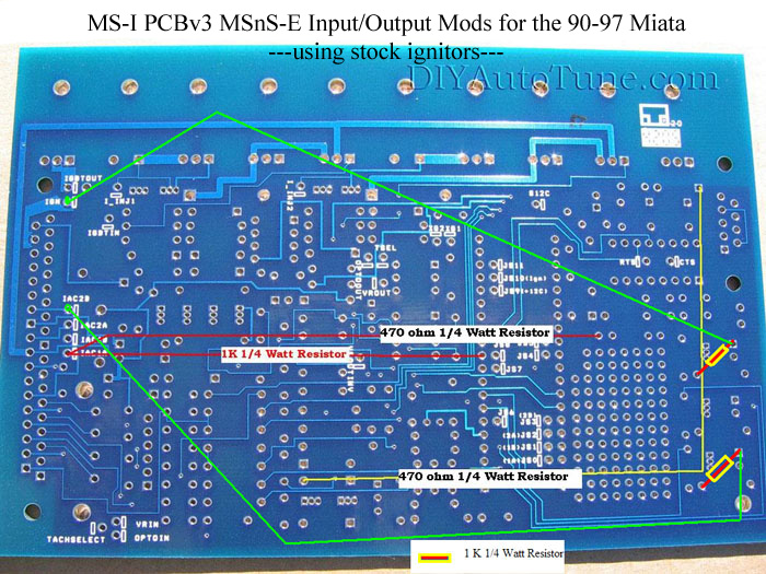
I'm pretty sure its wired like this document using the directions for a MS1 V3.0 using the factory two channel ingiter driving two dual post coils running the engine in wasted spark mode like stock. The wires and resistors follow this pattern:

My bottom right two resistors are not exactly the right value (1k) or equal. The bottom right measures 990 ohms while the one above it measures 850 ohms. The bands are the same colors. The other resistors are all in agreement with the specs in that image.
What does the Miata use for a spark driver?
Is this a CAS?

In reply to bentwrench:
I
Tach Input Background: Crank Angle Sensor (CAS) Wheel in the 90-97 Miata
There are two 'sets' or 'rings' of holes in the optical CAS. The outer ring of holes is read by an optical sensor and then sent across a wire to the ECU and referred to as the CKP signal. Likewise the inner ring with two holes is also read by an optical sensor, sent across a wire to the ECU and is referred to as the CMP signal.
Outer Ring - Crank Angle Sensor (RPM) - CKP
Inner Ring - Top Dead Center Sensor - CMP
Some years used a Hall effect signal instead of an optical sensor, with a pair of stamped steel trigger wheels. Although this one looks different, the signals are the same from an electrical standpoint.
MS1 - Getting the Tach Input Signal:
Run MSnS-E and the "2nd Trigger" Wheel Decoder option (where the missing tooth on the wheel decoder comes from a second sensor, usually cam position). The CAS has a CMP and CKP signal, so you take the outputs of each and run them into the MegaSquirt. Take the CKP signal (4 holes in the Optical sensor wheel, the "outer" ring of the CAS), and run it to the primary tach input on the MS with a 12v pullup resistor - then you take the inner ring of the CAS (1 hole in the sensor wheel) and run it to the secondary tach input on MS (it's pin 11 on the MS-I cpu) with a 5v pullup resistor.
If you follow my documentation for the mods below you'll externally wire the tach inputs like this:
The Primary tach input (CKP) (Reported to be White on Miatas) is connected to pin 24 on the MegaSquirt's DB37
The Secondary tach input (CMP) (Reported to be Yellow on Miatas) is connected to pin 25 on the MegaSquirt's DB37
So are you seeing RPM in TS when cranking?
If you see RPM and sync the input side is good.
In reply to bentwrench:
The controller isnt near the car at the moment.
Does anyone know if we should see a trigger or tooth wheel signal under "Diagnostics & High Speed Loggers"? We currently get nothing, just an empty box.
MrJoshua wrote:
In reply to bentwrench:
The controller isnt near the car at the moment.
Does anyone know if we should see a trigger or tooth wheel signal under "Diagnostics & High Speed Loggers"? We currently get nothing, just an empty box.
To clarify-should I see a trigger or tooth wheel signal when using Tuner Studio on a megasquirt powered by an early MegaStim?
A Megastim will not provide complex crank & cam signals
JimStim v1.5 with the v2.0 firmware http://jbperf.com/JimStim/index.html
Theres a setting under the "spark" tab called "Stim for wheel" that I have to turn on to get an rpm signal using the Mega stim. I have it set to:
Wheel simulator-on.
Number of steps/outputs-4.
My understanding is that needs to be on and burned to the squirt. I don't know if that provides a signal that can be seen by the tooth logger.
MrJoshua wrote:
Theres a setting under the "spark" tab called "Stim for wheel" that I have to turn on to get an rpm signal using the Mega stim. I have it set to:
Wheel simulator-on.
Number of steps/outputs-4.
My understanding is that needs to be on and burned to the squirt. I don't know if that provides a signal that can be seen by the tooth logger.
You'd set it to 2 outputs. It would let you test the CKP input and spark outputs, but not the CMP input.
In reply to MadScientistMatt:
Do you have a step by step for testing the ignition circuit similar to that great link you provided earlier for the injection circuit?
Cross posted on the MSExtra support forum. Had no datalogs or MSQ's to offer. 
You need datalogs and msq's.
Cant seem to ever get a log of anything other than the tooth logger and my testing setup doesn't give a tooth signal.
You can't just do a "regular" datalog in stim for wheel mode by going to the datalogging menu in Tunerstudio?
Hopefully we fixed it. Building backup just in case.

Yeah.....I should never be a surgeon.
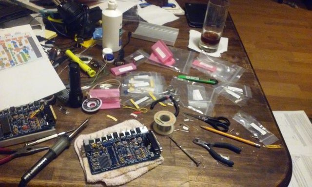
Hopefully the dark liquid in the glass is whiskey and not just straight Coke.
Stampie

SVreX
MegaDork
9/5/15 9:02 a.m.
Exciting.
I'm standing by my mailbox...
...with a whiskey in my hand! 
In reply to MrJoshua:
That reminds me of the warnings on gas cans that say "Gasoline and fire don't mix!"
Well, no, they really do. Very energetically actually. What other things are you warning writers lying to me about???
Almost done with the backup squirt, ran out of parts.  Need a TIP 122 for idle control (could possibly use the BIP373 I'm not using for ignition but it seems like overkill
  ) and a .1uF capacitor used for the "cap mod" described here that is used to quiet a noisy ignition signal.
So I guess that actually leads to a couple of MS questions:
1) Is a BIP373 a reasonable substitute for a TIP122?
2) I have 2-.001uF 100V caps, 1-.01uF 50V cap, and 1-.22uF 50V cap.
a) Can I make something resembling a .1uF 50V cap out of those?
b) How much capacitance do I really need to quiet the signal?
Bought parts for a JimStim as well so I can test things more thoroughly in the future.
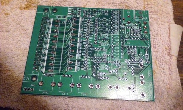
So if you inhale enough solder smoke this:

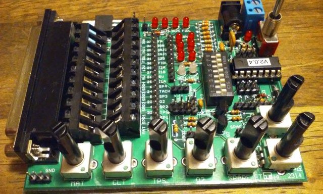
Becomes this:

JimStim!
I'm getting a little better at building this stuff.....I hope. I just wish I was getting faster. 
Well now you're drunk and you have 2 MS's and 2 stims, is the car running yet?
bentwrench wrote:
Well now you're drunk and you have 2 MS's and 2 stims, is the car running yet?
The cars still in GA and all the MS's are still with me in FL so not yet. We are hoping to do two events next weekend so hopefully one of these things does the trick.


