My set-up in a 1967 MGB-GT race car:
-1986 Mustang 5.0 engine(block,heads,cam all stock '86)
-GT40P upper/lower
-3/4" intake spacer
-65mm BBK TB
-70mm MAF
-Painless wiring harness
-Tweecer programmer
-Reconditioned computer
My MAF signal is .3 volts at idle and goes up to .5 volts at a steady 3000 rpm, I am told that it should be .8 at idle and go up to 1.5 at 3000 rpm. I changed to a new-in-box MAF, changed the program, changed all my ground connections and have double checked for intake leaks. Any ideas why the signal would be so low?
You can see pictures and video of the entire build V8 Powered MGB-GT

Nashco
SuperDork
12/6/11 8:52 p.m.
Have you checked the actual vacuum (with a gauge)? How did you check for intake leaks? Why are you checking MAF voltage? I assume it's not running properly, might be worth giving more info.
Bryce
Is the 5V reference good?
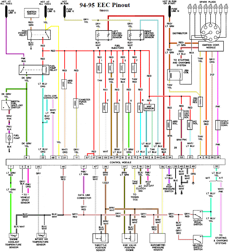
Second truckster. IIRC the ECU supplies 5V reference to the MAF and the return side voltage to the ECU is how it knows what's shakin'. So you should have 5V from the ECU to the corresponding pin on the MAF, then the return side to the ECU should vary depending on what the MAF 'sees'. It shares this 5V reference with all the other sensors, according to this diagram.
EDIT: Should have looked closer, no it doesn't. it seems to have its own dedicated 5V reference and also a 12V power. Looks like the light blue/red to terminal 50 and the tan/light blue to terminal 9 are for the MAF. If the IAT is in the MAF, it uses the black/white and then gray as its connections.


xFactor
New Reader
12/7/11 6:21 a.m.
If the maf is in an intake that is different than the one it's calibrated to, the output voltages will be different too. It sounds like it's in a bigger housing.
later, matt

Ford MAF's are built with hot element sensing (Bosch AFAIK).
Basically current to flows through the sensing wire to maintain a fixed temperature. As air flows past the wire, it removes heat, and so more current is required to maintain the fixed temperature. The change in current indicates the magnitude of the airflow, but it's not a linear relationship.
There is some serious active analog signal conditioning circuitry built inside.
So the supply voltage runs the works inside, and it calculates a linear output signal that is proportional to the airflow.
Notice from the wiring diagram above that the MAF power source is switched, fused 12V, reference voltage is 5V as described. Either one could be an issue.
The pipe routing upstream of the MAF can be critical too, the stream flow to the MAF should be uniform, or at least consistent.
How (and where) are you measuring the signal?
Are you using the stock EEC-IV setup?
Output impedance of the MAF circuitry is fairly high, so any loading (from analog meters, or auxilliary circuits) can degrade the signal.
Does the TwEECer let you display what MAF the voltage ECU sees?
I use an OBD interface to a laptop that lets me monitor and graph various ECU signals, can be very useful for troubleshooting.
Carter
Check the reference voltage and all of the grounds.
It turns out that the program reading the voltage was wrong, the actual MAF voltage is great. This is very frustrating because I replaced the MAF and re-did all the ground connections trying to fix the problem. Anyways, it's all good now.


