why the small 1310 yoke?
In reply to patgizz:
I caught a lot of heat about that, but Ron (CP champ that sold me the trans setup and driveshaft) uses 1310s, even in the new EM car (670 hp is the rumor). He's never broken one.
On top of that, it's a cheap driveline fuse and 5lbs lighter.
Cars like yours are why I always come in dfl in c prepared. I drive mild pro-touring cars on all seasons.
Are your lower links curved or are my eyes berkeleying with me?
In reply to Dusterbd13:
They are straight. The iphone might distort it a little. Potato quality photos.
Thanks!
Made another quick trip up because I just couldn't leave the suspension halfway (well, it's less than halfway, but you know what I mean).
I cut out the rest of the top of the subframe connector for clearance, and then made a new harness bar and support for the forward mounting point of the upper link.
I still have to make the lower mounting point and test the suspension range, but this should give you an idea of how things are going to look.
It also looks like I need to order a longer upper to get things where I want them (forward mount is set VERY high right now).
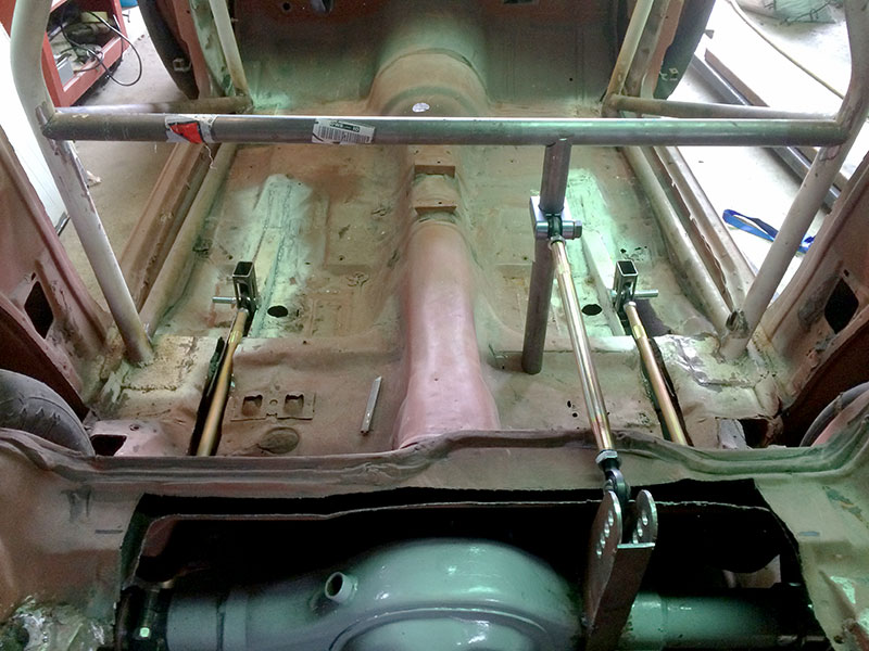
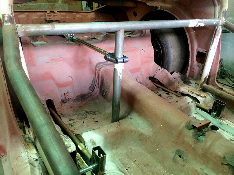
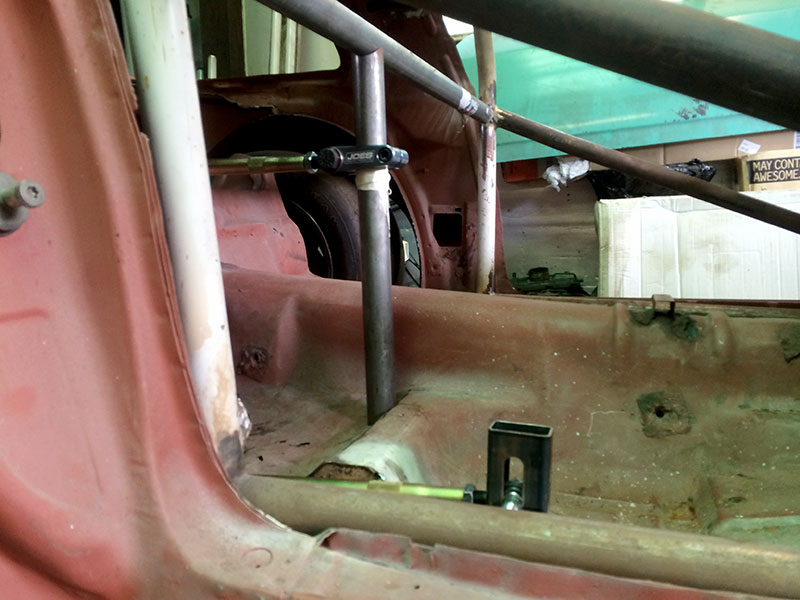
It might not look like much, but it technically rolls now.
Granted, the springs are a little stiff-
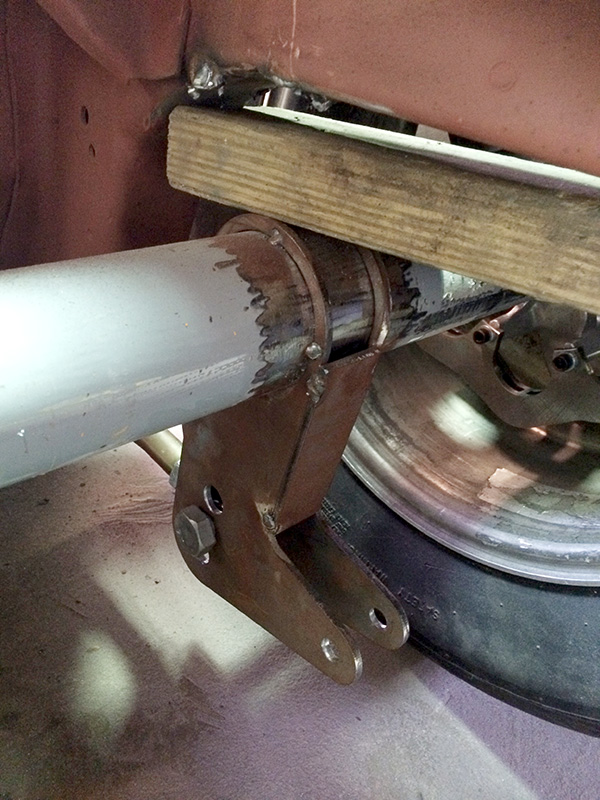
Took another trip up today to trim some metal for clearance for the diff and upper link.
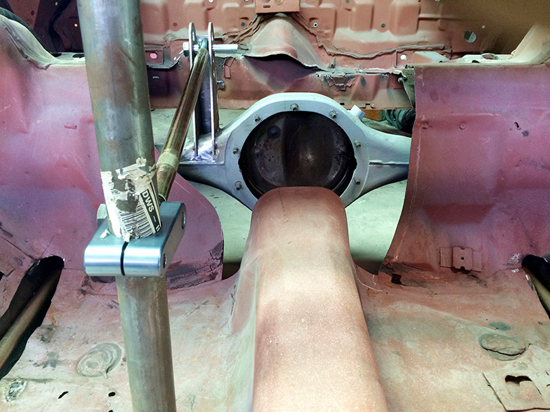
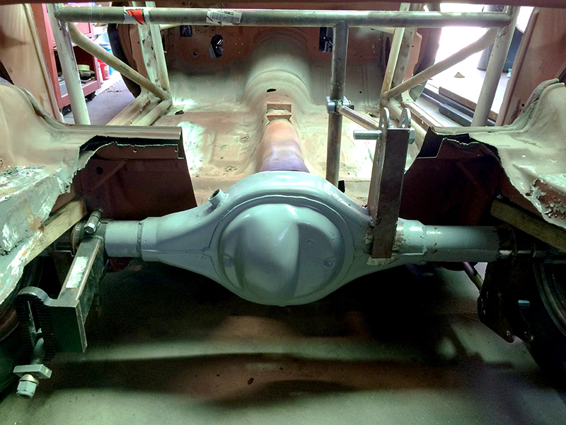
You might be able to tell by the ride height, but I will be raising the trains tunnel soon.
I also had to fab up a lower crossmember to support the tube that the upper link rides up and down on (in previous photos it was actually cut long and sitting on the ground). This should also act as part of a driveshaft loop.
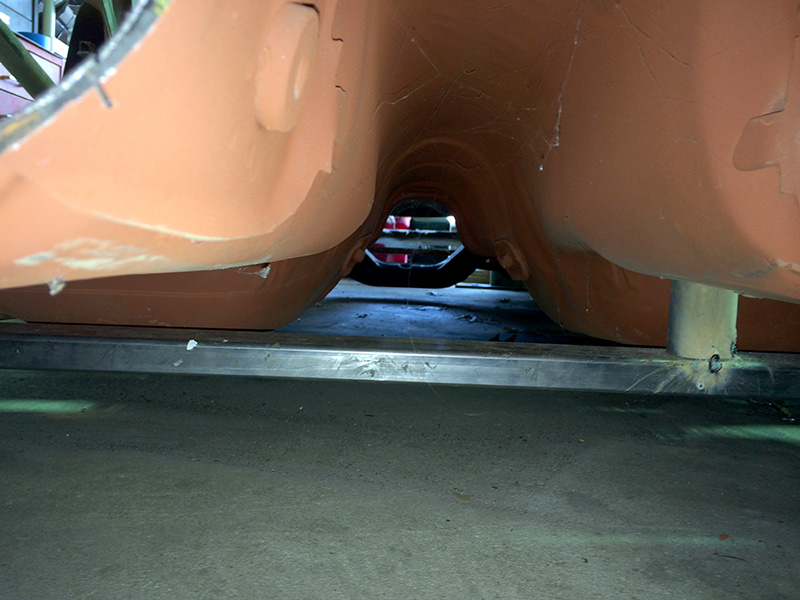
You can see through it through the hole in the floor.
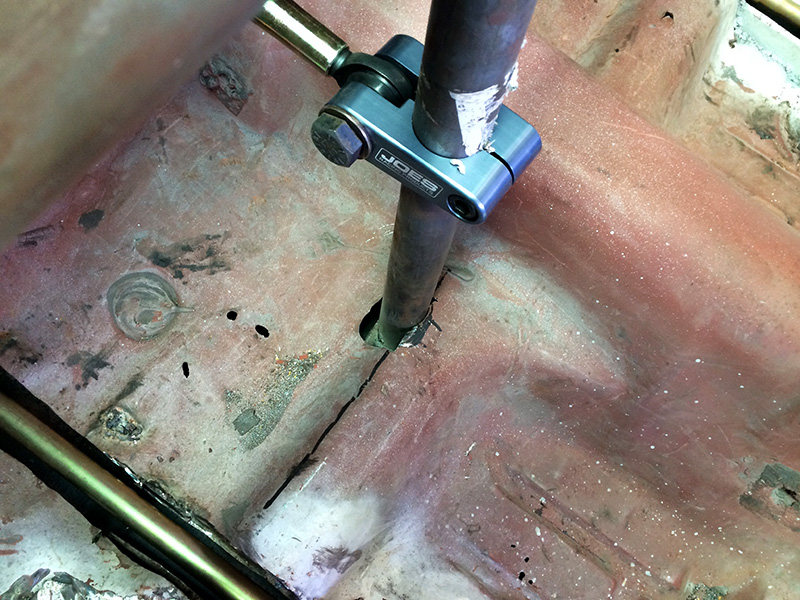
And finally, I cut a little more metal to allow for some travel so that the body wasn't sitting on the tires anymore. Still more trimming to do, but I need to finalize the wheelbase first.

I seriously spent about 10 minutes just pushing the car forward and back. Felt awesome.
Made it home from the 2014 SOLO Nats!
I had an absolute blast making my C-Prepared debut. Look forward to more updates on my build soon. I'm motivated, to say the least.
Huge thanks to Randy for letting me use his awesome Camaro.
Here is video of my two days: https://www.youtube.com/watch?feature=player_embedded&v=QoEupZGMz9k
Here is my video of the parade: https://www.youtube.com/watch?feature=player_embedded&v=nAb2637EU_8
Gimp wrote: The nice part about the circle track stuff is that it's so cheap I can always get close and try again.
I'm with you on that one. One of the things I like about my Troyer Hillclimber. I can replace the whole suspension for less than some guys are spending on a few pieces of theirs.
Got some more work done, but not too much too see. When I cut out the old cage, I never cleaned up the bits that were left attached to the landing pads and the main hoop. My laziness finally caught up, as I had to spend a good bit of time cleaning this stuff up, and by the time I was done I was out of blades and cutting wheels, meaning I couldn't get as far on the rear structure as I was hoping.
I did manage to get the start of the upper structure (2x2 square tubing) roughed in. The tube meets up at the node on the main hoop with the harness bar, and has to slope up, so it took some planning and careful cutting/notching to make it work. The uppers are long for now. I have to figure out where the uprights will land before I can get them in place.


This rear structure will end up building a box around the rear end, and things like the coil overs, panhard bar, and fuel cell will all mount to it.
I also installed a "new" set of stock door hinges and marked the fiberglass door with where I have to drill holes to make them work. The stupid pegs that were on the door for mounting just won't cut it. I took the doors back home with me so I can create the backing plates, get things drilled, and setup so the next time I'm up there I can hang them.
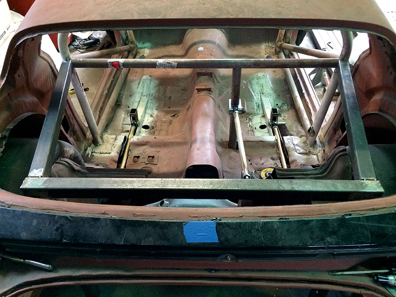
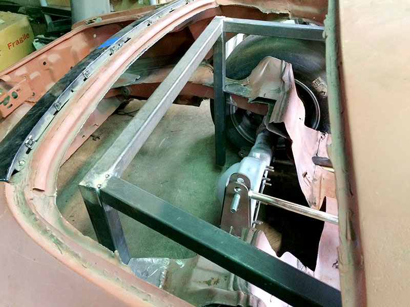
More updates. I went up on Saturday and got a good bit of the "box" for the rear suspension done. This mess of square tubing is necessary to support the coilers, rear location device (watts or panhard), and connect the back of the frame to the front when I remove the portions of the framerails for coilover and axle tube clearance. Next time I go up, I'll build the bottom of the box and put in some coilover mounts, and have this thing close to being on "suspension."
From above:
From the side:
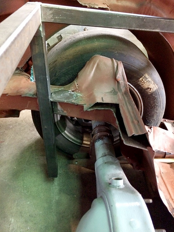
From the front, looking toward the back.
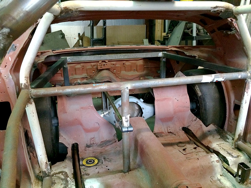
From the rear (the "legs" are long right now. They will be boxed in at the bottom next time.
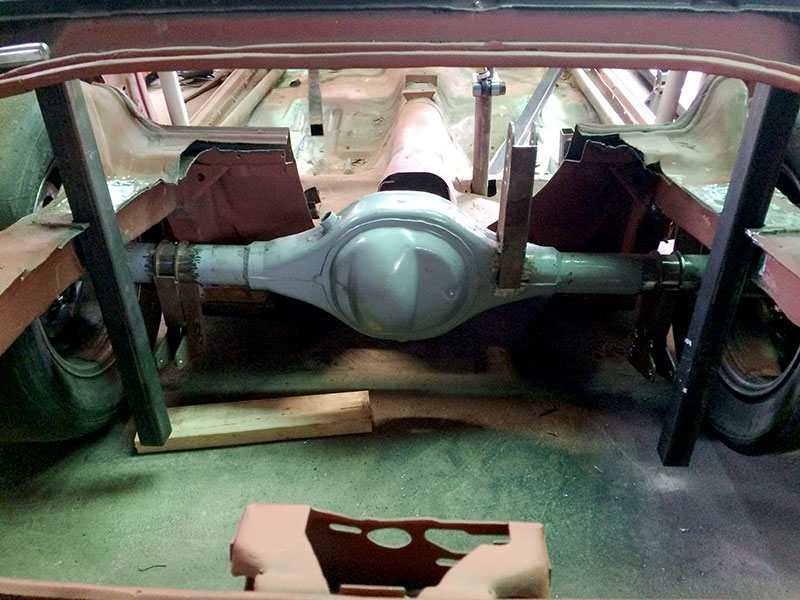
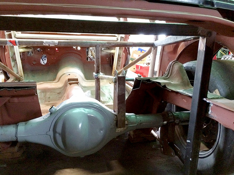
Still chipping away. Went up this weekend and got the "box" all put together (aside from welding it completely in - everything is just tacks or interference fit).
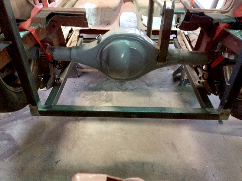
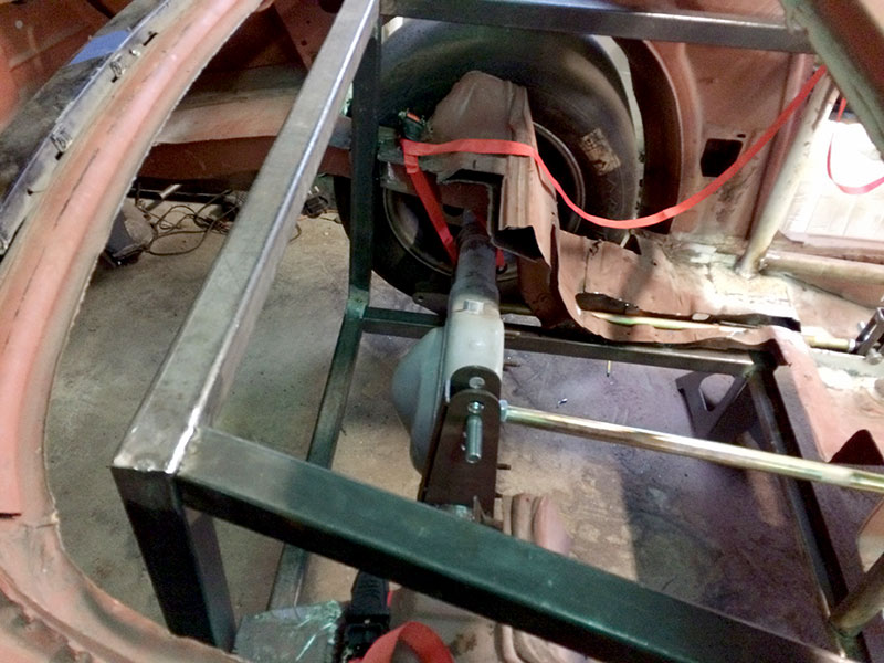
Part of this meant cutting away more of the floor. Until next year, removing this much floor was a bit on the illegal side, per the rules. That changes next year. Removing this much had always been my plan, in order to make fabrication easier. I just don't have to put it back back now. Battery, ballast, and exhaust will all occupy this space now.
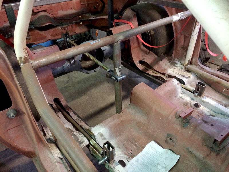
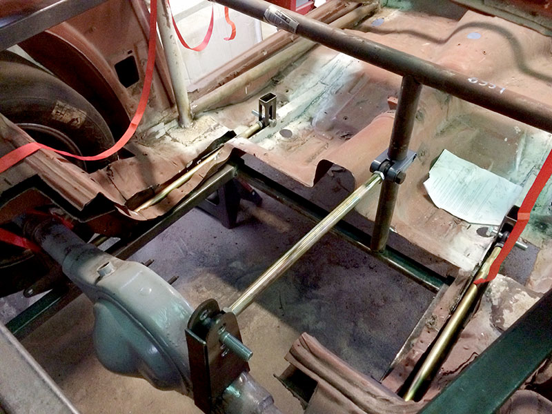
Probably won't get back up there until December, due to the holidays and November being a very busy month for the cancer foundation. I did bring home the fiberglass doors and hinges, so at least I'll have something to work on if I have a free moment. Pictures of that stuff soon to break up what has become a very boring thread.
I'm happy to report that I can actually get the rear end out of the car, but it is (currently) tight!
Hubs and brakes have to come off, and the pumpkin has to be out, but it just sneaks by. It will be a little better once some frame clearancing for travel is done.
My buddy inspected my work yesterday, and signed off on the design so far. He's an accomplished welder, so he's going to get it all stuck together for good by early December. Then we can get shocks mounted up and make this a roller for good.
In the meantime, brown santa has been very busy. I'll get some pictures of shiny things soon.
mazdeuce wrote: Still following along. Still want to build a CP car someday.
If you ever want to drive one, I suggest buying. ![]()
It's getting close to Christmas, so parts are starting to show. I've got some stuff that I won't be using for a while (steering bits, headers, ignition stuff, etc), and some other parts that will get mocked up soon, like my tiny little fuel cell (5 gallon).
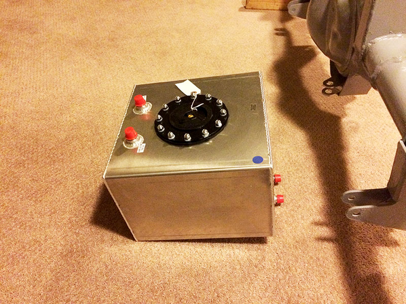 He's so cute...
Speaking of mockups, I "won" a plastic SBC off eBay. This should help me get things like the exhaust and steering mocked up.
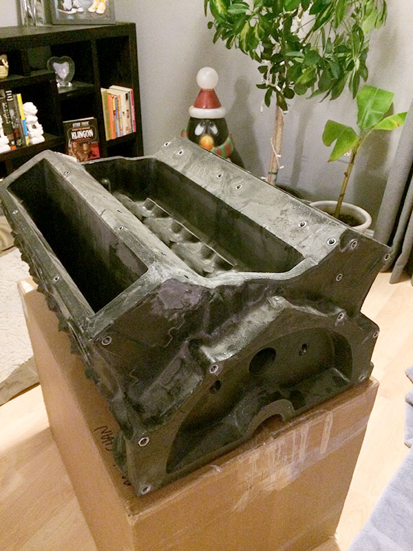
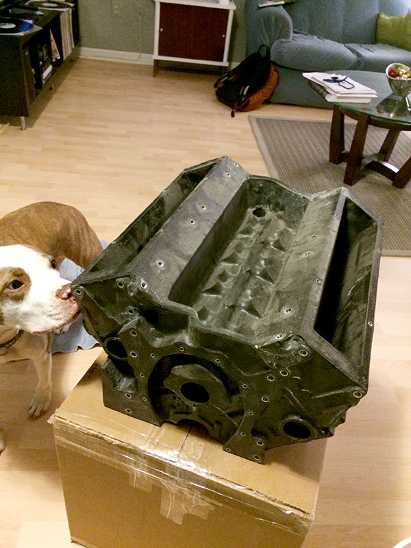 Otto approves...
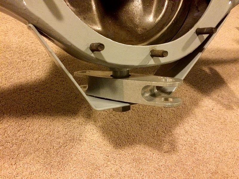
Now, onto fabrication stuff. My friend Larry of Casey Design (the guy who drew up the brackets on the rear for me) did the finish welding of the brackets, and fabricated the mount for the underslung Watts link. Savvy readers will notice that I had been planning on a panhard, but both packaging and tolerances to the rear structure pretty much forced my hand. The "propeller" is from Jim at Fays2. Once it was all welded up, I took it home and painted it for hopefully the last time. The rear brake caliper brackets will be clamp on, so there shouldn't be further need to weld on the rear.
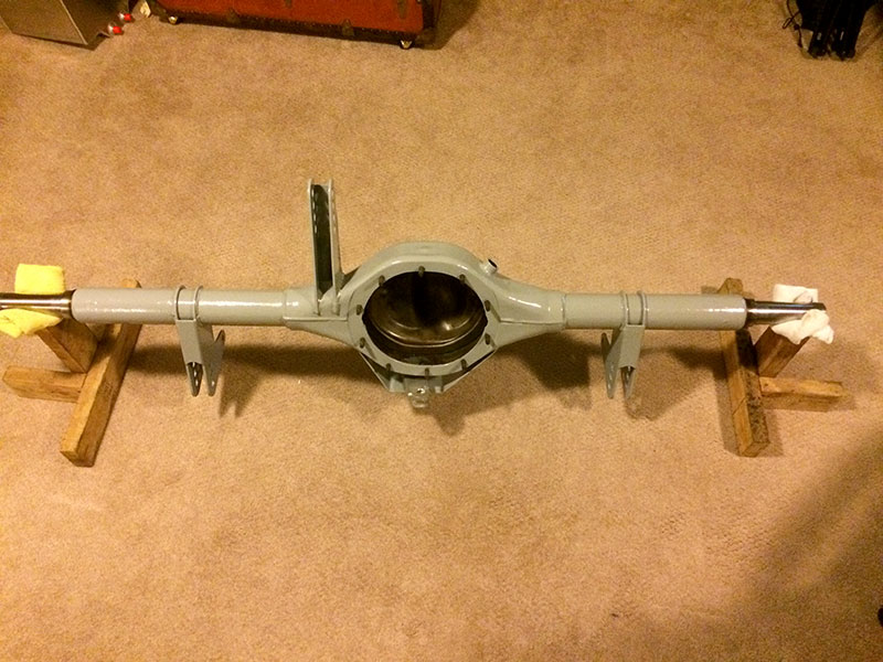
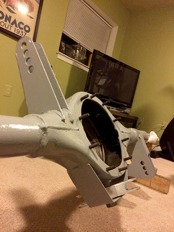
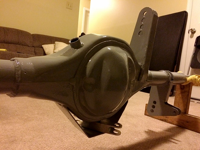
I should be heading back up next weekend to get some more of the structure welded together so I can work on the coilover mounts and remove the bits of frame that will be in the way.
Good thread so far, car looks tough as nails! This might be a dumb question but I'm a n00b to old American stuff, and have no idea what the thing on the bottom of the diff casing is and what it does. I'm curious! Could you enlighten me?
I have done a little fabricating in my time though, and would say that gussets are your friend on anything like this!
Stumc,
Its the lateral location for the solid rear axle,which has been mounted on the bottom of the housing for a low roll center.
See http://en.wikipedia.org/wiki/Watt%27s_linkage
^^^ What he said.
The propeller is from the Fays2 kit (the owner of the company sells the individual pieces if you ask nicely).
The two major differences are the Fays2 kit mounts the pivot to the chassis, and places it behind the rear end in a vertical path (with adjustments for roll center). You could also argue that the pivot is being held in single shear.
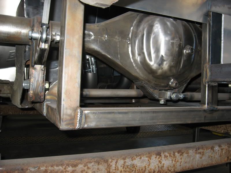
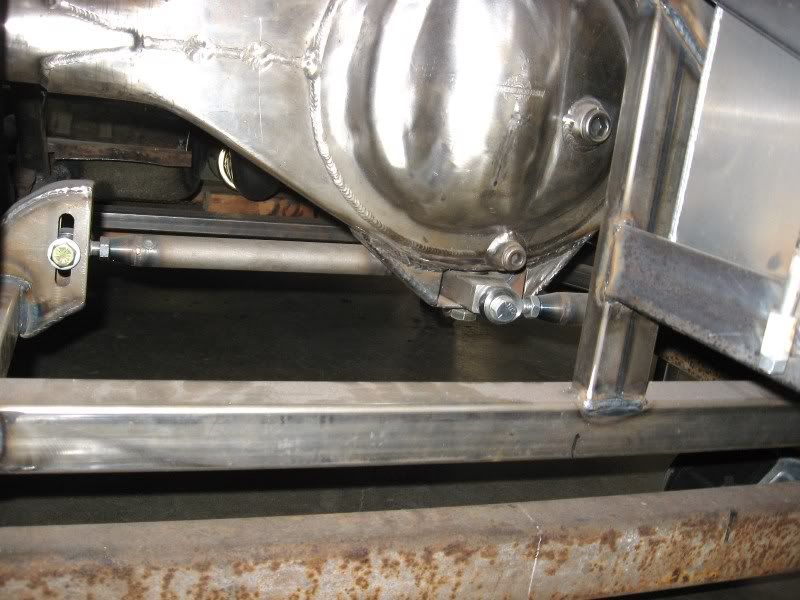
My choice to go underslung was for both packaging, and for roll center considerations. I've also mounted the pivot to the axle, with the other ends attached to the chassis. There are debates as to which one is better, but I'm largely copying what I've seen on other race cars. We also added an additional support to put the mount into double shear.
Of course! Seems obvious now. I've seen setups where something similar is mounted on the back of the diff casing, with the pivot longitudinal, inline with the props haft if you know what I mean. I've also seen setups where there's simply brackets fixed to the diff, one mount above the plane of the axle and one below, which it guess achieves the same thing, but what would be the advantages/ disadvantages between running a pivot versus a fixed bracket?
Pardon my ignorance and don't mean to hijack the thread!
I think you are talking a panhard bar versus a watts link...
If you think about it there is a range of movement through the swing of a panhard bar's range of motion (isnt much, generally negligible, but us racers want the last nth). The pivot setup (watts) does not have the lateral movement at all.
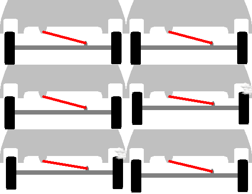 Versus

That being said, the lateral movement from a panhard on Gimpy's car would be small.. We are only talking 3-4 inches of vertical motion over a fairly long panhard bar (well as long as could be fitted). It just turned out to be easier to package the slightly better performing, but more complicated Watts link setup.
Stumc wrote: Of course! Seems obvious now. I've seen setups where something similar is mounted on the back of the diff casing, with the pivot longitudinal, inline with the props haft if you know what I mean. I've also seen setups where there's simply brackets fixed to the diff, one mount above the plane of the axle and one below, which it guess achieves the same thing, but what would be the advantages/ disadvantages between running a pivot versus a fixed bracket? Pardon my ignorance and don't mean to hijack the thread!
Almost what my compatriot said. Joe thinks you're talking about a panhard, but on a closer read you are describing a traditional Watts link.
The traditional (mounted to the diff cover) and the "underslung" work the same. The underslung gives you a packaging advantage (in some cases) and a lower roll center.
Don't worry about the highjack at all.
I'm basically stealing this design:
AH!, right! Are you asking the advantage of mounting the football (pivoty thing) on the chassis side vs the axle side?
See, pivot vs bracket got me thinking Panhard. There's a bunch of ways to accomplish lateral constraint, some better than others.
The mount on the chassis vs mount on the axle opinion largely depends on who is selling you the Watts link. Whatever they make is the superior product.
In all Watts links, the center of the pivot is the roll center.
"Chassis-mounted pivots have a consistent distance from the sprung mass to the roll center because the pivot (roll center) moves up and down with thesprung mass.
Axle-mounted center pivots have a roll center height that is fixed at some point above the ground. So, as the body moves up and down,the distance between the sprung mass and the roll center will change.
The reason that a consistent distance from sprung mass to roll center isimportant is that the sprung mass acts on the suspension through that distance. So, a consistent distance means consistent suspension loading,which leads to consistent tire loading and better overall vehicle handling." - Steeda
When I read that, I couldn't make sense of it either.
I saw it like this:
-- The roll center was lower with the underslung
-- The packaging was easier with the underslung (in my case)
-- The fast guys are doing the underslung, so that must be the jam, right?
You'll need to log in to post.