1 2 3
EvanB
EvanB GRM+ Memberand PowerDork
1/13/13 9:03 p.m.

99 rail and 94-97 FPR are what you want. I had to cut down the vacuum nipple to allow the hose to fit when I installed mine. I installed it with the fuel outlet pointing down and the vacuum nipple pointing toward the head.

Edit: I see what you are talking about now. I ground that down to fit the fuel rail. I just expanded the area that is already cut out exposing the bolt until the manifold fit if that makes sense. No problems with it yet.

peter
peter HalfDork
1/13/13 9:23 p.m.
EvanB wrote: 99 rail and 94-97 FPR are what you want. I had to cut down the vacuum nipple to allow the hose to fit when I installed mine. I installed it with the fuel outlet pointing down and the vacuum nipple pointing toward the head. Edit: I see what you are talking about now. I ground that down to fit the fuel rail. I just expanded the area that is already cut out exposing the bolt until the manifold fit if that makes sense. No problems with it yet.

OK, I wasn't sure if you'd have run into the same issue with the MSM - I don't know what parts are different on them.

I mocked it up a couple ways, for some reason I feel like my FPR allowed me to have the outlet down and the vacuum away from the head. It'll be close in both places, but plenty of meat to grind away there.

EvanB
EvanB GRM+ Memberand PowerDork
1/14/13 12:26 a.m.

Yea I can't remember which way the vacuum nipple was pointing but the outlet was definitely down and I had to trim the vacuum nipple. I tried to grind away as little as possible from the intake manifold and was very careful tightening it down and it hasn't given me any problems.

peter
peter HalfDork
2/2/13 5:00 p.m.

OK, so I haven't been out to the garage since the last update, but I have made some progress here in the city.

I followed Frank's build guide for the MS3X, mostly. I left out the LEDs and the serial port as they're not visible or needed. I also used the standard DB37 rather than stuffing the connector into the case.

Everything tested out fine on the bench, but when I flashed the firmware to the MS3, there was a pop and a lot of smoke.

Capacitor C16 exploded and C17 got toasted in the crossfire. Interestingly, when I went to clean the explosion residue off the bottom of the MS3 daughter card, I found some crud that looked out of place

Closeup (Holding a magnifying glass in front of a mild-telephoto lens is an amazingly usable macro lens). There's a solder bridge between two vias right next to the four pins from the USB port on the other side.

After talking with the ECU gurus over at MiataTurbo, I replaced C16 with an up-rated cap (33uF, 35V tantalum, DigiKey #399-3584-ND) and C17 with the standard part (718-1168-ND). Some solder wick, rosin, and patient heat cleaned up the excess solder, and this time the firmware flash went without a hitch.

I'm waiting to see what the under-dash connectors look like before I build my connector pigtails. I didn't know that the wire bundle from the footwell to the behind-the-seat ECU could be unplugged from the rest of the harness. If I can do that, I'll trim that bundle up and connect the few wires I'll need from the 94 harness to the DB37 for the MS. Love plug and play!

peter
peter HalfDork
2/2/13 5:05 p.m.

While I was screwing around with the MegaSquirt, I sent my injectors out to be cleaned. In all the test-fitting of the fuel rail, I managed to mangle one of the rubber bushings on the head end of the #1 injector. That, combined with the fact that these are 12-year old injectors that have only done 18k miles, allowed me to justify the $16/each cleaning fees.

They weren't bad to begin with, as expected, but I'm glad that one outlier was caught and brought up to spec.

It's always nice to start with parts you know are good!

peter
peter Dork
2/15/13 7:35 p.m.

OK, finally got back out to the shop, armed with a dremel and a silicon-carbide burr. First thing was to grind away at the intake manifold to get it to clear the fuel rail. Amazingly, I didn't take a "finished" picture, but suffice to say that I simply ground away the bit of the manifold that was hitting the fuel rail. Here is the 99 fuel rail with my '94 FPR attached.

photo (7)

You can see the paint I put on the fuel rail to check clearance to the intake manifold. After doing this several times, I got to where there was visible light between the two, so hopefully there's little chance of parts rubbing and wearing through. That would be bad.

Also note, I didn't have to modify the intake manifold for the FPR vacuum source, just some gentle bending of the tube.

Edit: For the connection to the 99 fuel rail, should I be using these connectors to convert from the quick-disconnect style of the 99 rail to the '94 clamp-style? I don't want fuel spraying everywhere...

peter
peter HalfDork
2/15/13 7:55 p.m.

Next up was the wiring nightmare.

More questions later, but first, pictures of stuff that I definitely didn't know existed.

Not that I doubt Keith, but I'd never heard that the Miatas with ECUs behind the passenger seat used a separate wiring run for the ECU. This could make wiring in the MegaSquirt much, much simpler!

Except that it's a total bitch to get to.

Here's the deal.

This is the passenger foot well. To orient yourself, the tan trim piece in the lower right corner is the trim directly below the glove box and in front of the passenger door. The black plastic box on the left side of the screen is the thing that holds the A/C bits. What you don't see is the blower motor housing, which I had to remove to gain access to this stuff.

The harness comes out from underneath the carpet at the lower left corner of the picture, and has three connections to the body harness: two blue connectors in the center of the frame, and one large white one just to their right, slightly shadowed.

Pop those off and undo some connectors (don't forget the headrest speaker connection!) and you get this.

From left to right: two yellow ECU connections, one white headrest speaker connection, one white harness connector, two blue harness connectors.

Really, I'm amazed. Unless my plans change, I'll cut this up and use this as my pigtail into the DB-37s for the MS3.

So remember how I had to remove the blower motor box to get to this stuff. That was fun: the two out of three nuts holding the blower motor in were easy to get to. The third involved removing the airbag. Which wouldn't have been so bad had it not taken me a good half-hour to undo the orange airbag connector. (I eventually realized that the rubber boot was preventing the release tab from operating correctly. Got it!). When I finally wrestled that damn box out of the way, it was disgusting inside!

All sorts of junk got in here and it looks like mice actually got in and pawed away at the foam on the recirc door. Look at that! I scraped off all the brittle old foam and washed everything with hot soapy water. I didn't have much success with the fan blades, mostly because I wasn't able to pop them off the motor. I may go and see what a new motor/fan runs, in case that's easier than cleaning all those damn plastic mouse-piss-soaked blades. Also, this is the original motor, who knows how much longer it will last.

So... not all that much accomplished today, but I did learn something new about Miatas. And I probably caught hantavirus. C'est la vie.

peter
peter HalfDork
2/15/13 8:09 p.m.

Question for those of you who have done this before:

How the berkeley do you get wires through the firewall?

After playing footwell gymnastics all afternoon, I still can't get a good look at the grommet where all the stock wires come through the firewall. And that's a big, tightly-wound bundle to boot, so there's no way I'm going to get the old wires out without cutting.

The MiataTurbo guys seem to think some form of merging is in order, which sounds to me like splices in the engine compartment. Which seems to be exactly what I don't want to do.

Emilio used the VVT wiring and made a new hole in the firewall.

Cute, but too much for me. I'd have to pull the dash and that's just not going to happen.

If you don't mind me calling you out Keith, can you expand upon "I grabbed the engine harness out of the donor car, two wiring diagrams and merged them. "??

Many thanks!

GioA
GioA
2/21/13 10:52 p.m.

I stumbled upon this thread for searching some VVT related stuff, but I just swapped in a 02 VVT motor into my 94' Miata so I'll let you know exactly how I did. This is a very straight forward swap and I think you are complicating yourself for nothing. I've been running my motor for a few months now but it's running on all the 94' electronics. This means that my VVT isn't hooked up yet and I'm using the old style CAS instead of the crank and cam trigger that the VVT motor has.

There really is no reason to pick and choose wires and essentially create a new wiring harness. Especially, since you plan on using a MS3 this makes your life significantly easier. You can splice in the VVT cam and crank trigger and the VVT solenoid through the CAS wires from your 94' harness. Just search on maitatubo.net for the diagram or explanation on it. You can also splice in VVT coil-over-plugs into your 94' coilpack wiring. You also don't need to worry about losing your tach signal since your MS3 will take care of that. Use you 94' throttle body, but I think you can splice in the wires from the VVT throttle body into the 94' harness if you choose to. Swap the coolant sensor and temp sensor from the back of the 94' head into the VVT head. Use the 94' alternator and oil pressure sender and preferably use the VVT starter cause its smaller and 3 lbs lighter.

Sorry for the long post but that should cover just about everything. I removed all the emissions stuff from my car so that was one less thing to worry about. I did my swap without cutting a single wire, but as stated my VVT isn't hooked up yet. To sum it up use every single plug from your 94' except splice in the VVT cam/crank trigger, vvt solenoid, and coil-over-plugs. Hope this helped.

Keith Tanner
Keith Tanner GRM+ Memberand MegaDork
2/22/13 10:35 a.m.
peter wrote: If you don't mind me calling you out Keith, can you expand upon "I grabbed the engine harness out of the donor car, two wiring diagrams and merged them. "?? Many thanks!

I'm not going to give you a step by step like "take the blue wire with the white stripe and move it to position 4W". Partly because what I did for my Hydra wouldn't match what you need for your Megasquirt.

I took the engine harness out of the donor car. This provided me with the engine end of all my wires. Using the wiring diagrams, I determined what wires I was going to need for what sensors, then ran them to the correct place on the ECU terminals. That's it. It's detail work, but it's not difficult to understand the big picture.

The Hydra that I used typically sits on an extension harness. I had the connectors and simply attached them to the ends of the wires running to the engine. Not with splices, but but crimping on ECU terminal pins and slotting them into the connectors. Just like the factory does. You could do the same for the MS by buying a few dozen inexpensive ECU pins. Electrically speaking with regards to the engine, my 1990 is now a 2004. It's a bit more work, but the end result is much cleaner and less prone to problems.

I did cheat and use a 1994 alternator, but there's no reason why I couldn't have controlled the 2004 one with the Hydra. The MS may not have that ability.

GioA's method of ignoring the hard stuff will work as well, but you should definitely hook up the VVT and the associated sensors if you have the choice. For the VVT to work properly, you should use the cam sensor on the intake cam as it's part of the feedback system for the VVT. The crank sensor is also more accurate than the CAS on the back of the intake cam.

peter
peter HalfDork
2/22/13 12:13 p.m.

Thanks guys.

After writing the above posts and realizing no one was paying attention, I didn't update with my latest, simplifying decisions. I followed up with the MiataTurbo.net guys and brought this thread back to life and got some great feedback.

Keith - thanks for the help - I wasn't looking for a wire-by-wire instruction, I just couldn't figure out how the hell I'd get the donor engine harness through the firewall without a hole saw. It's not exactly a clear (or short) path.

GioA - Your method jives with the Andrew (Savington) method and is what I'm going with. Once I pulled the injector/coil/coolant-sensor harness off the '94 motor, I realized just how simple this will become.

Plan:

  • cut off connector pigtails for '01 coils, splice to '94 injector/coil/coolant-sensor harness.

  • re-purpose EGR, evap, etc wires for power, signal, and ground as needed, splicing on '01 connector pigtails to retain '01 crank, cam, TPS, IAC, and VVT bits.

essentially, the connectors on the engine will be a mix of '94 and '01 pieces. The wires through the firewall will all be '94, repurposed for my unique situation.

I'm tempted to cut the ECU extension harness I pulled out above and solder the relevant wires to the two DB-37s that the MS3 needs. But if I ever need to edit things, pulling that run from the blue connectors to the DB-37s will be a bitch. I could shorten it and crimp on ECU connectors, but that adds another place where things can fail, and I've never been a huge fan of the female end of that equation - the female connector is supposed to be PCB mounted and in a high-vibration environment, "solutions" like this make me uncomfortable. (though this is one of the best jobs I've seen)

Anyhow, that's just me grousing. I think I should just cut the extension and solder directly to the DB-37s. I shouldn't be making changes that often, and pulling this stuff the second (and third, and fourth...) time(s) should be much easier, now that I know the tricks.

Keith Tanner
Keith Tanner GRM+ Memberand MegaDork
2/23/13 10:07 p.m.

I don't remember exactly how I bought the wires through the firewall, so it couldn't have been that traumatic!

No hole saw was involved, it was probably one by one through the existing grommet by the fuse box after I pulled the original wires out. I was trying to avoid splices wherever possible. I've got full function using all the appropriate 2004 sensors (other than the alternator) - which makes life pretty easy now, as I'm dealing with more of a purebred than a mutt.

peter
peter HalfDork
2/23/13 11:35 p.m.
Keith Tanner wrote: I don't remember exactly how I bought the wires through the firewall, so it couldn't have been that traumatic!

Considering you've forgotten more about Miatas than I know, I'm not sure this is a valid measurement

Keith Tanner wrote: No hole saw was involved, it was probably one by one through the existing grommet by the fuse box after I pulled the original wires out. I was trying to avoid splices wherever possible. I've got full function using all the appropriate 2004 sensors (other than the alternator) - which makes life pretty easy now, as I'm dealing with more of a purebred than a mutt.

After your earlier encouragements, that's the way I wanted to go on this, but after looking at the actual wires, I realized I'd need to pull the dash to do the un-wiring and gain access to the cockpit side of that grommet. I just don't have that kind of space and time.

My Saturday night was spent working on a wiring spreadsheet for this swap. It's not really terrible at all. I think the biggest time sink was getting comfortable with the grounds.

My Saturday nights were much sexier when I had a job.

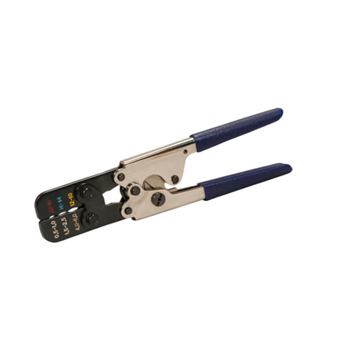
Also thread relevant: ordered this crimper and some heat-shrink butt connectors. It did a marvelous job on the cheap Rat-Shack connectors I tested it on. I've been trying to pull them off their wires all weekend to no avail. Winner!

peter
peter HalfDork
2/23/13 11:42 p.m.

Also, ordered and received this fuel line part from Amazon. According to the guy who advocated my current wiring plan, this is what I need to convert my quick-connect '99 fuel rail to my '94 hose-clamp body. Hope it works!

(Dorman 800-120)

I also ordered the $6 fuel line disconnect tool, but this adapter doesn't seem compatible with it. Hmm.

Keith Tanner
Keith Tanner GRM+ Memberand MegaDork
2/23/13 11:55 p.m.

I didn't have the dash out of my car. FYI. It was all done with minimal disassembly. I usually remember the difficult solutions, the easy ones I don't because I know I can figure it out again

You can buy "fuel line repair kits" at NAPA that will convert a push-on fuel rail to a hose barb. Nice solid fit on the fuel lines. Also FYI.

When crimping, I like to use a ratcheting crimping tool. They don't let go until you've hit the required squish. Mine's got interchangeable jaws for different types of connectors. Thumbs up for heat shrink connectors.

peter
peter HalfDork
3/9/13 7:41 p.m.

A day at the garage, but nothing much accomplished. I spent the day standing/sitting in the engine bay with a plastic scraper, bits of old towel, and WD-40. I thought the black paint in my engine bay was matte or semi-matte. Turns out with some elbow grease, it's actually glossy. Soft though - I found lots of scrapes and scratches, and I think the plastic tool even left a few of its own.

Still better than what was there before.

Having received my latest box of goodies from FM (really miss Turbo's "signature" on the invoice), I wanted to drop the rack in with the new poly bushings. I have a new steering-shaft to rack u-joint, as the old one had some stiction to it, but the new part refused to go into place!

After much cursing and about 1000 degrees of test fittings, I discovered that while the entire steering shaft is splined, there's one spline on my u-joint that wasn't cut/broached/whatevered! Not sure if this is a manufacturing error or whether I got the wrong part, but I'm unhappy. In theory, the engine could be going in tomorrow if not for this screw-up!

Also, I spent some time looking over an old California Racer Special to see if we could find any markings to prove its history. My car will never race with Phil Hill and Carroll Shelby, but it might be cute to hide a unique mark somewhere...

peter
peter HalfDork
4/5/13 9:58 p.m.

I'm an idiot. The steering part was right, I just wasn't fitting it right. Got that finished up last time.

I only got a half-day in today, but I did manage to get a little accomplished. One noteworthy item, for anyone pursuing a VVT swap.

Remember how the water neck on this motor was snapped off in the accident? I replaced it with the part number from a 90-00, because the 01-05 part wasn't listed on the Rosenthal website, and the ones I saw elsewhere were 50% more expensive. I thought all water necks were the same. They're not.

Here are the two mixing manifolds that live right off the water pump, between the power steering pump and the A/C compressor.

The one on the right is from the 01 motor, the left from my 94. There is a very large change in the diameter of the tubes for the bypass pipe.

Since I used the old model water neck, I needed the narrower 90-00 hose and the old mixing manifold.

I guess this could throw off my cooling a bit, but not enough for me to worry about. Should only come into play when the thermostat is closed. Fingers crossed!

peter
peter HalfDork
4/7/13 9:15 p.m.

Summary of my progress this weekend:

Motor is in. Engine bay wiring is complete. Fuel lines plumbed. New clutch slave, eliminated crazy-straw coil at the slave with a 949 racing clutch line, to go with the 1.6L Fidanza flywheel and ACT clutch of some kind (used). Lots of little things.

I'll post a full write-up of the exact wiring changes when this runs, but the changes have been quite simple. Up front, the IAC and TPS changes were dead easy. I repurposed the 12V + signal lines from the "Pressure Regulator Control Solenoid Valve" for the VVT. This is the doohickey that lives in the intake manifold valley on the 94, and the wire length and location was just perfect for the VVT oil control valve.

Here's a picture that shows a bit of the rewiring, plus the odd path the fuel line now takes.

I actually got to speak with Keith The Legend on Friday, about an issue I was having with the new steering rack bushings. Torque wrench wouldn't give when tightening up the mounts. It felt like I was continually squishing the urethane. I was wondering if this was normal. Apparently it's not. I'm not a gorilla, but I did manage to strip a couple threads on one mount. A quick spin with the proper tap, some new bolts and some Loctite fixed it. I'm now wary of the shop's big torque wrench. Seems to work at lower values, but I'm questioning the higher range.

Lots to do yet, but finally progress in the right direction!

peter
peter HalfDork
4/7/13 9:18 p.m.

One issue I haven't seen addressed: my throttle cable is far too loose with the new motor in. Searching reveals this may or may not be common to NB->NA swaps, but it seems more prevalent with NB->1.6L NA swaps. Not sure if I need an NB throttle cable (is it shorter than the 1.8L NA cable? Dunno) or if this part from FM will do the job. May have to email FM.

Keith Tanner
Keith Tanner GRM+ Memberand MegaDork
4/7/13 9:37 p.m.

Yup - that's exactly why that part exists. The throttle cables have different dimensions. That particular bracket does assume you have our 1/2" adapter on the car, though.

In my case, I grabbed the throttle cable out of the same car that donated the engine.

peter
peter HalfDork
4/7/13 9:46 p.m.

I tried the bracket swap and discovered the distance between the two bolts that hold the bracket to the manifold differs between brackets. I didn't think about slotting one hole so it would fit. Not sure if that would give me enough distance or not.

The FM part is labeled as for a 1.6L cable on various 1.8L engines, so I'm confused on whether it's appropriate here with my 1.8L NA cable on my 1.8L NB engine. If I had a 1/2" throttle body adapter, that would take up the slack I have. If this part assumes that adapter is in place, then would it really do anything for me? I guess I'd need to know how much slack it takes up on its own...

peter
peter HalfDork
4/7/13 9:50 p.m.

And as an Easter egg for those still following this rather unpopular thread, I got a ride in this on Saturday. It's one of the cars whose home my projects occasionally (frequently) invade.

Click pic for video of it running.

It's... a monster.

Keith Tanner
Keith Tanner GRM+ Memberand MegaDork
4/8/13 8:39 a.m.

Note that I said I swapped the cable, not the bracket.

Right, I forgot this was a 1.8 car to start with. So the FM brackets may not work. But if you change the cable, it's all factory-fit. Or show a bit of creativity in adapting the bracket you have.

peter
peter HalfDork
4/8/13 9:27 a.m.

Reading comprehension fail. Thanks for once again pointing out the obvious Keith.

This car may have to pass a visual emissions inspection, so I want to keep the fabricated bits to a minimum. At least I have options.

Thanks Keith!

calteg
calteg Reader
4/8/13 11:42 a.m.

For the wiring bundle through the firewall:

Grease up the wiring bundle using the lubricant of your choice.

I managed to pop that rubber grommet out using a LONG flathead screwdriver, with a wooden block wedged against the firewall. Gave me enough leverage to work it loose.

I've also seen people take very small wire cutters and just split the top half of the grommet. Makes for very easy removal, and also allows you to add/subtract any wiring.

1 2 3

You'll need to log in to post.

Our Preferred Partners
BDHv0HCqVwdUskNJJB0wFTj6i8DEPu8HmRs6ITdQfGT9m7V89r0qGHMvY9bzaPwe