


Dusterbd13 wrote: Hydraulic or electric power rack?
electric power rack

Dusterbd13 wrote: Hydraulic or electric power rack?
electric power rack

Ok. Ill look around and see what i can find.

Toyman01 wrote: I have nothing intelligent to add to the discussion. I just wanted to say I'm glad to see this pop up to the top of the page on a regular basis.
I'm with toyman on this one.
The big problem, which I just realized, with this solution is that I need to make enough room for a nut on the threaded sleeve below the knuckle. I guess that's not that bad.
Almost a month later...
No pics today, but here is the deal. Terry borrowed an outer tie rod end and created a sleeve for me from a 3/4-16 bolt. I drilled out the taper in the drivers side spindle and tapped it likewise. Yesterday, the sleeve arrived. Tunakid #4 and I threaded in the spacer, and later, after two additional long-term guests, and their dog arrived, and unloaded everything they own which is not in long-term storage (no really, in the army between deployments) into my garage, I actually did creep back into the garage to do stuff.
After moving copious stuff out of the way, I assembled the steering on the drivers side and used the time-honored bumpsteer measuring method called "put your iphone on "compass" mode and push it against the disc while moving the spindle through its arc with a jack".
Anyway, tens of degrees of bumpsteer was measured with the tie rod on top of the spindle where the general put it. Where Tuna put it, on the bottom, with Terry's spacer, the extremely precise iphone could not detect a single degree of bumpsteer.
I will work on a more precise method, but I am obviously on to something here. I am super excited.

Yay!

Glad to see this thing still clicking along.

Excellent work. I love it when a plan comes together.

Your consistent progress is shaming me to get back to my build. Keep it up!

Always makes my day when the TunaTruck makes an appearance. More pictures please.
Pete
Agreed, can’t wait to see more
In paint by spring right? ![]()
In reply to NOHOME :
I've said that before, eh? This spring the Honda should be primed and painted, but golly my budget is stupid.
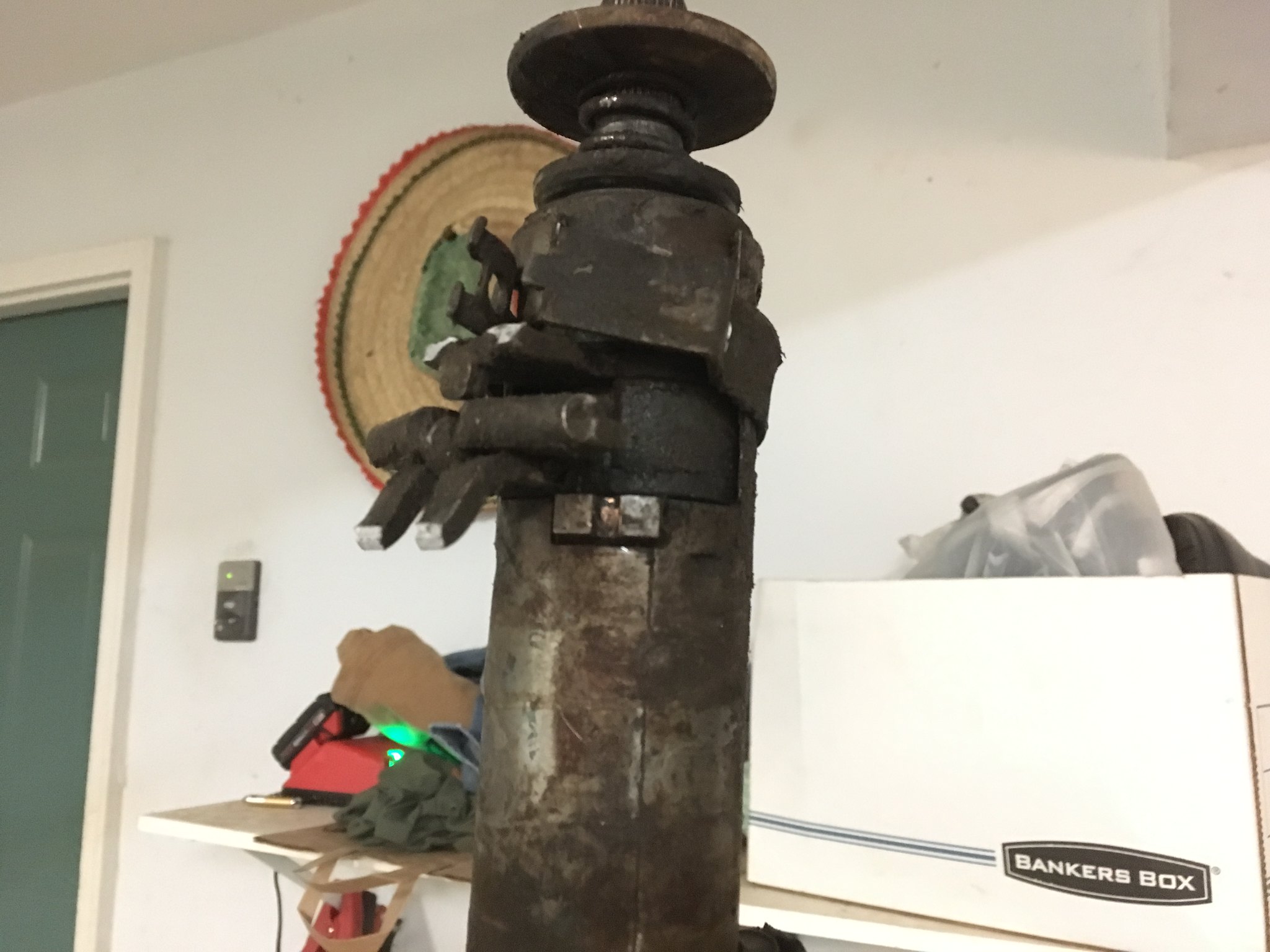
This area does not photograph well, and I had to truncate my video due to company wandering all over, but here is what I've got.
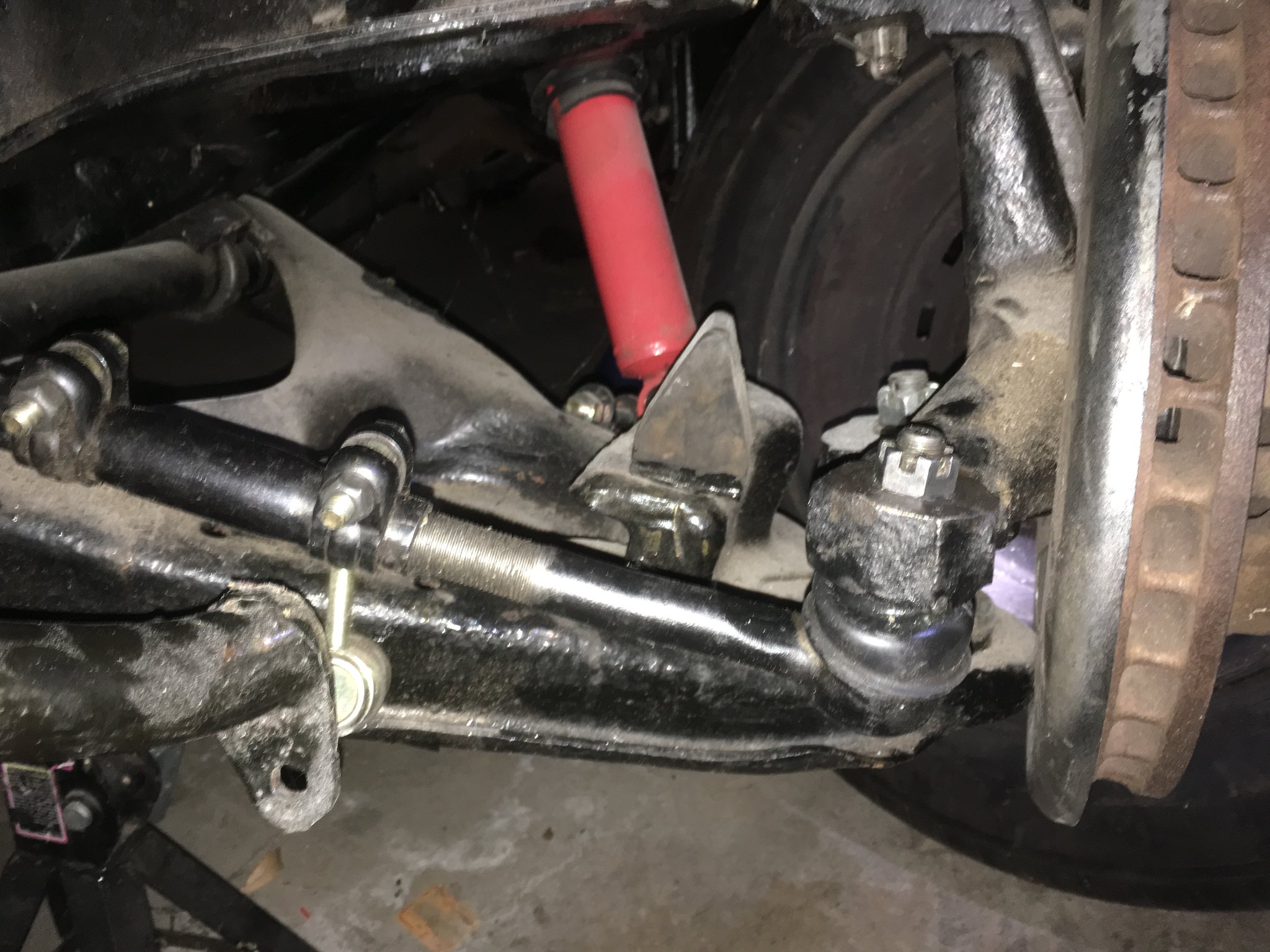
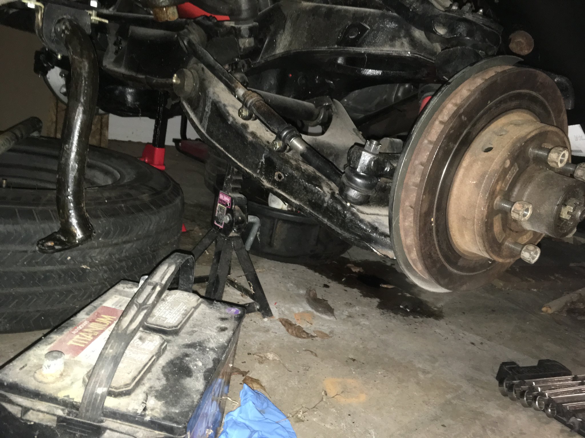
This shows the complete tie rod, hanging beneath the spindle, lower center of gravity!
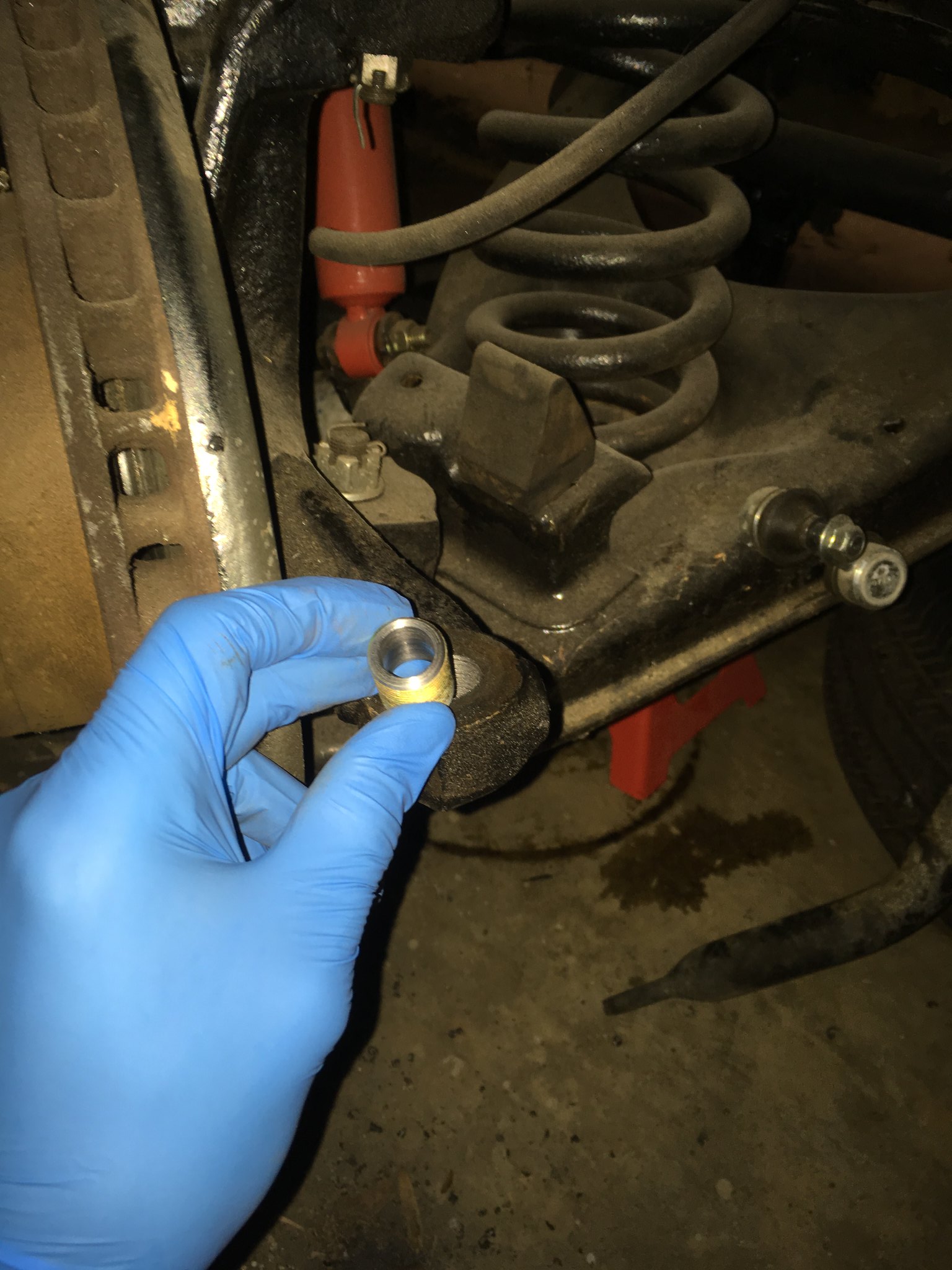
I did not take everything apart, but here is the threaded spacer in the spindle
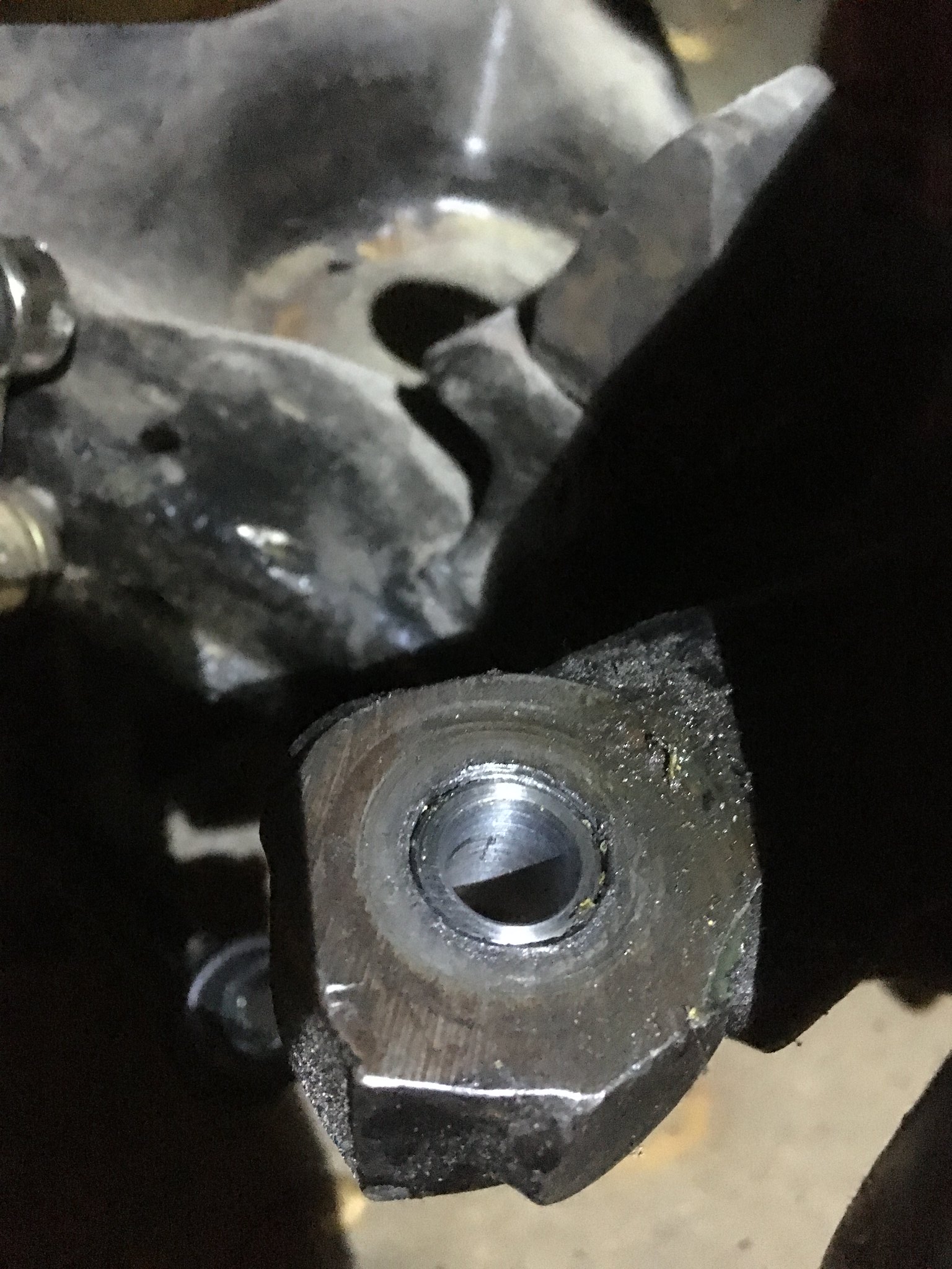
It's really quite simple. I think I have even devised a plan to measure the bumpsteer cheaply. I'll find out soon and show everyone when I've done it.
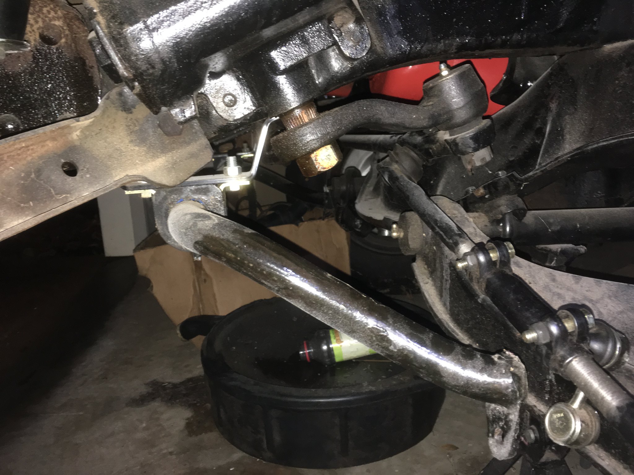
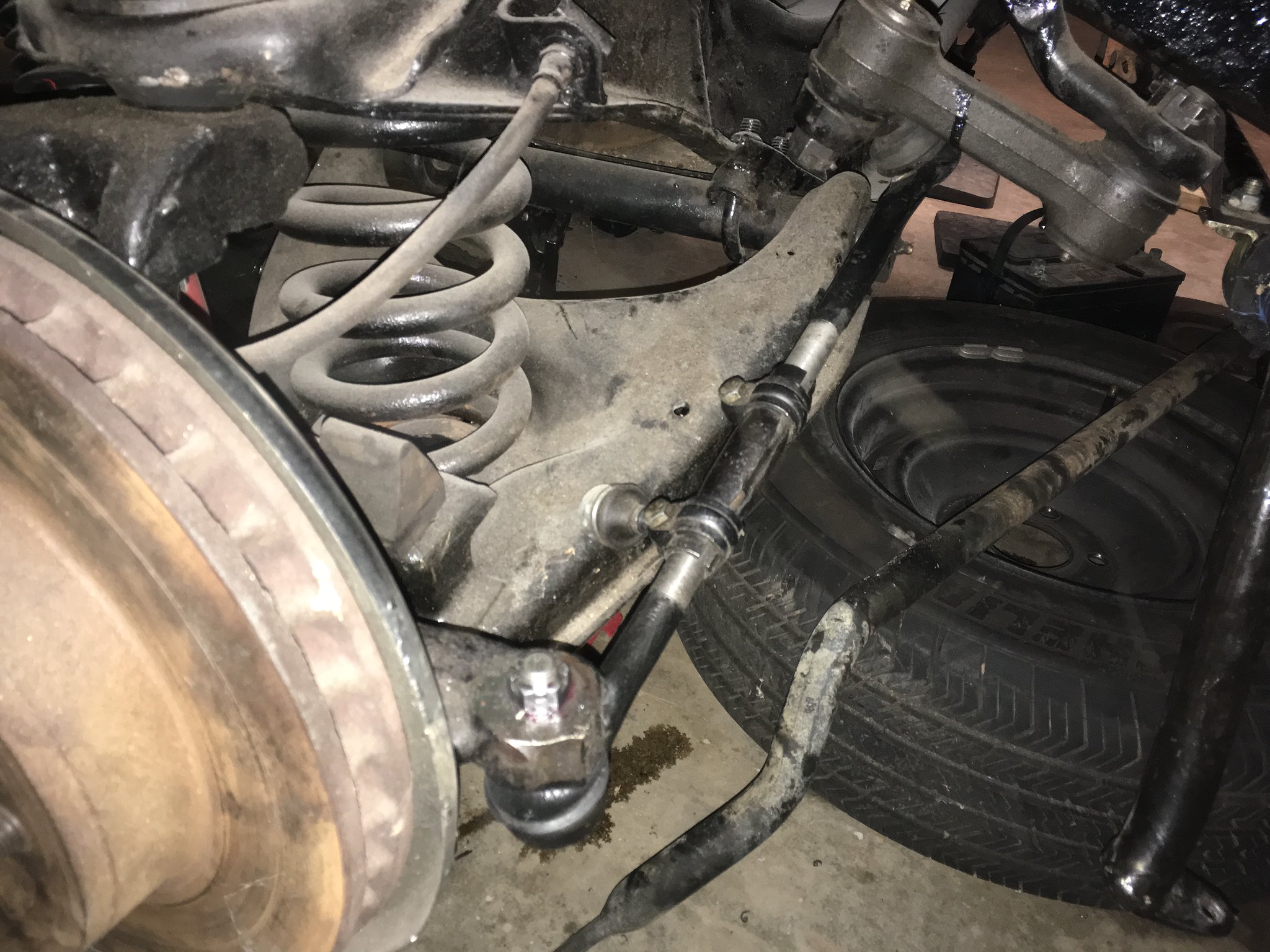
The problem now if that the swaybar hits the tie rod in its new location. The solution is that the swaybar, as designed by GM and not modified by me, will fit now. Observe.
If you recall, the swaybar originally looked like this
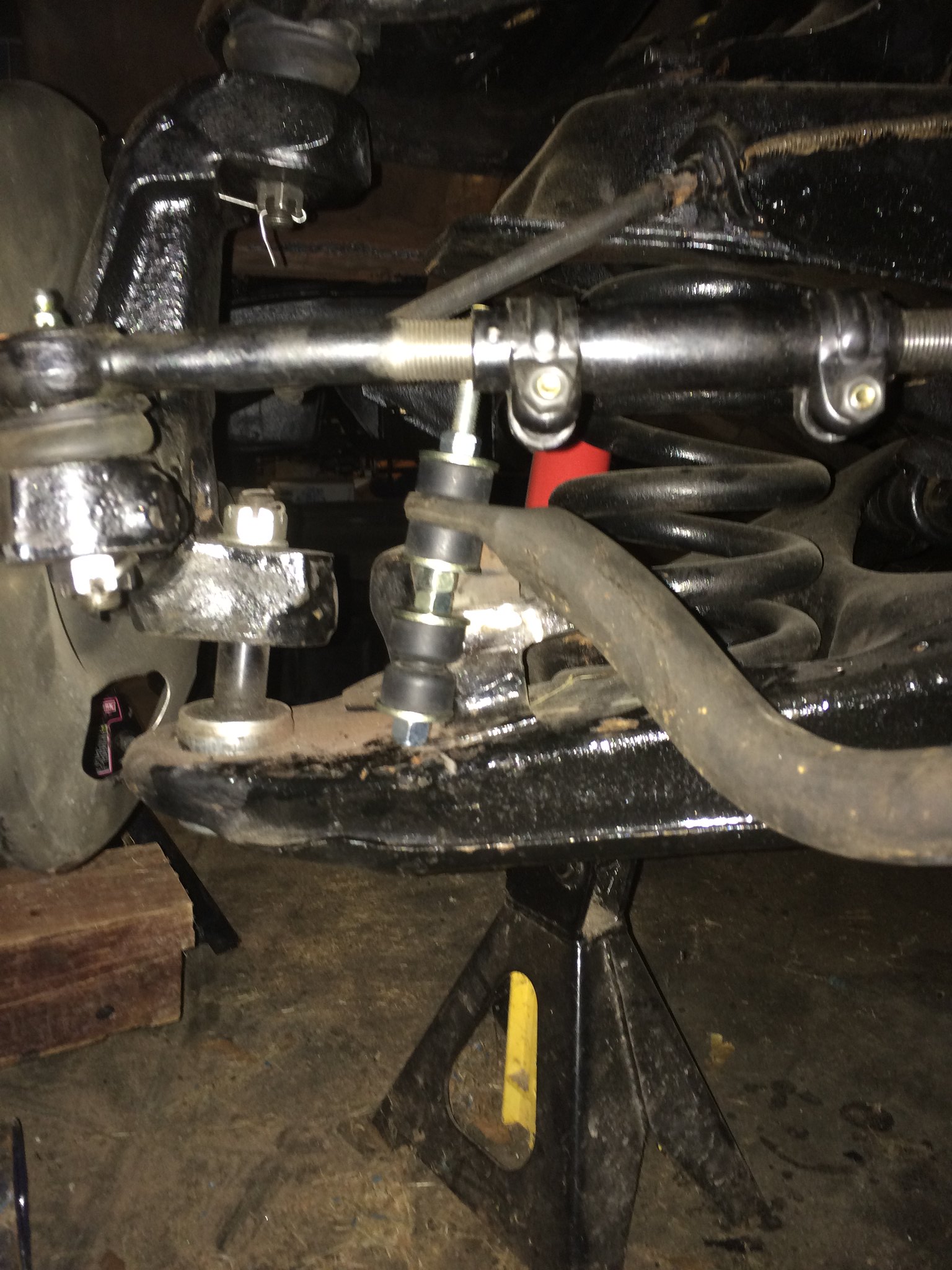
Please note that now the tie rod will handily pass beneath the arc of the bar. So really, the solution is to go get another stock bar from a 1996 Suburban. I only wish I could find a bigger hollow one for cheap. The stock endlink from that generation of truck (I believe 1992-1999 are all the exact same) will fit into one of the two holes already in the control arm for the style swaybar that GM used for the dump truck version of the generation I have. If you recall, those look like this.
So, off to the junkyard to get a swaybar again, measure bumpsteer to make sure it's as good as it looks, have Terry make a second spacer, and the front suspension is done.
Remember how I said they were the exact same? The one from the yard (which I actually cannot recall the exact year/model) was vastly different on the ends and actually didn't fit, so that puts me back at my modified one with longer end links. I can do this though, no big deal.
I took many many videos and pictures, some of which I will share later, but the moral is that my slick idea to measure the toe did not work.
Terry came through with another slick tapered/threaded spacer, so I went back, drilled and tapped the passenger side, and used red Loctite to insert it and assemble the tie rod. I also removed and reinstalled the drivers side with Loctite too. It's done!

Untitled by Brian Bassett, on Flickr" />
Now for my next trick...
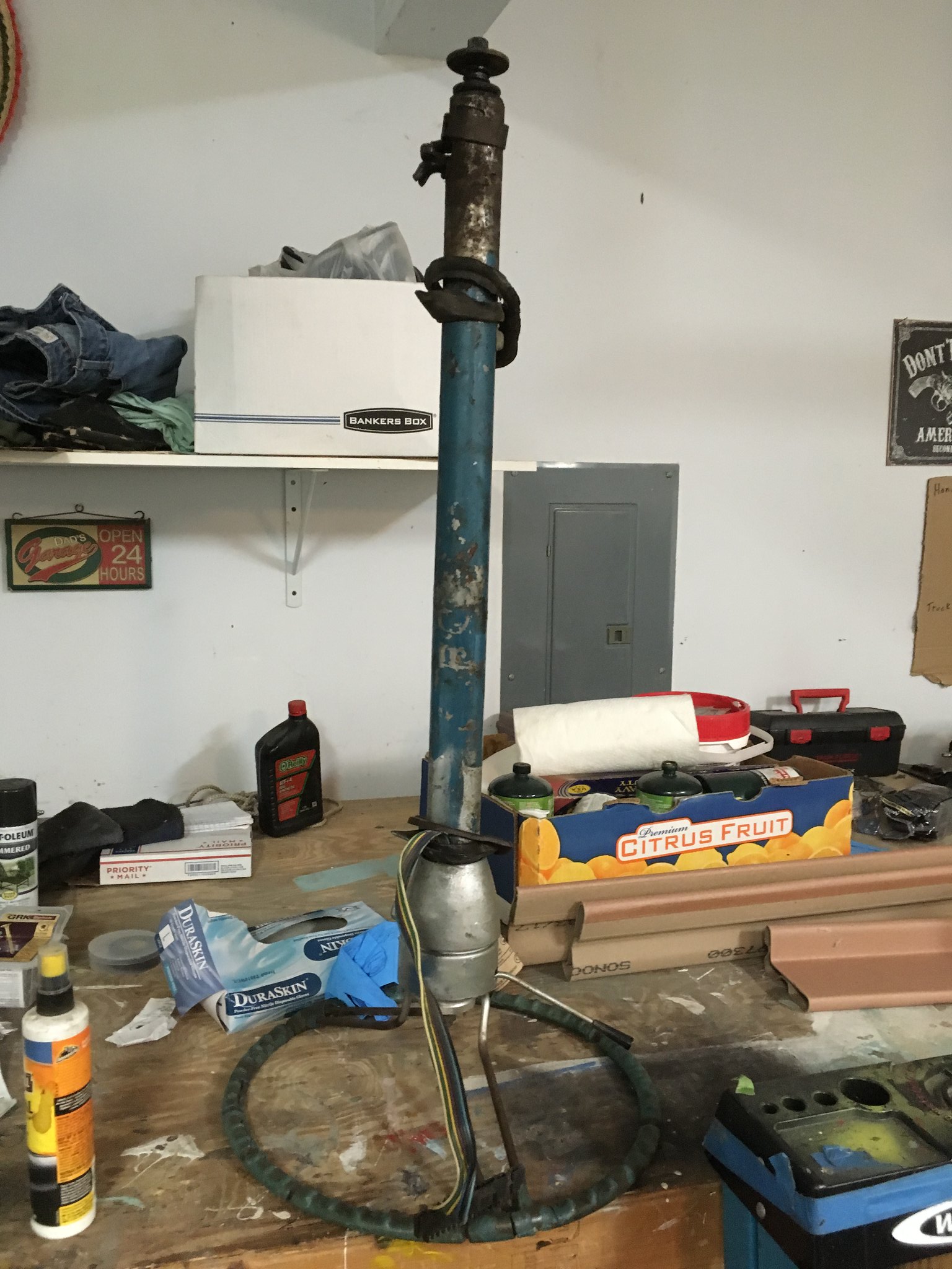
I have no clue what to do with it. That's not entirely true. I want to replace the lower shaft with the typical Cherokee shaft for the rag joint elimination. That's "easy". I also want to remove the evidence of the tree shift from both inside the cabin (the hole where the lever went) and in the engine compartment (the leftover levers) and fix the flashers (broken off). I am open to ideas which are nearly free.
For some reason my phone won't send the pic of the tapered sheet metal bit in the cabin where the shift lever used to live. Use your imagination.
In other news, my nine year old today hearing about garage work at dinner said "Dad, you got your mojo back!". That was cool.
Mojo back indeed!! You have no idea how happy I was to see this pop up again

Any concern of the new fitbit for the tie rods backing out over time? I knwo you red loctited them. Just thinking a large washer between the castle and the bits would mean it would have to crawl it's way out against something stopping it from rotating out.
In reply to Mad_Ratel :
A washer on the castle but side makes sense. I can’t use one on the tie rod side though. Good call. I’ll get something going.
I do wonder about the threads pulling out of the spindle. But this should see none of the force of a lca or uca. So probably no issue of the threads getting ripped out.
In reply to Mad_Ratel :
It’s an inch long 3/4-16 thread. It’s stronger than the cast iron around it. As long as it doesn’t spin out, it should be fine. The loctite should be more than sufficient to prevent that even without the washer but it’s still not a bad idea.
I was thinking more of thread pullout, but as I said, it's not teh same forces a UCA/LCA Balljoint would.
The washer should stop any loosening of the thread insert.

I would think that a well placed center punch between the sleeve and knuckle, along with the loctite would keep everything in place. There should be no torsional load on the sleeve once in place unless the tie rod end was to lock up for some reason.
Personally, I believe the red loctite will keep it in place, but belts and suspenders never hurt anybody.
There ain't no kill like overkill!
You'll need to log in to post.


