1 2
adoyle88
adoyle88 New Reader
4/16/15 7:55 a.m.

Most of you probably know my dad and me from our other thread about building the DF Goblin (if you don't want to read the thread you can get a quick rundown at our site DF Kit Car) and you've all probably noticed that we've been a little quiet. Well we haven't had much to post about the car because we've been busy building a CNC bender for about a month and a half.

So why did we decide to build a bender rather than buy one? (I can't believe anybody on the GRM Builds and Project Cars forum would ask such a question, but I'll answer anyway)

The CNC benders we browsed through cost too much and were overqualified for what we needed to do. When we were building the first Goblin, we made things easier for us to manually bend by designing each piece to be bent in a single plane. We are sticking to single plane bends in the production frame, so we don't need a full 3D bender.

Here's the requirements we designed the CNC bender to meet:

  • low cost
  • able to bend 1.5 inch and 1.25 inch tubing
  • chain driven feed system capable of moving the tubing >200 IPM
  • easy to load
  • hands off operation after loading the tube

With these requirements in mind, we bought a few hydraulic cylinders from Northern Tool and some DIY CNC supplies from Probotix (I highly recommend Probotix for CNC projects, they were incredibly helpful). Then we got on Solidworks and drew a bender around these parts. Here's a mostly complete model:

bender 3D model

A basic rundown of whats in the image, starting from the left:

We have a single bending ram that rotates the bend dies (we have two dies because we went with a "double barrel" design that has dies on one side for 1.5 inch tubing and dies on the other side for 1.25 inch tubing. This way we don't have to change out anything to switch between tubing sizes).

Attached to the bend dies are clamping rams that hold the tubes to the bend dies. Also attached to the bending dies is a homemade optical encoder that measures the bend angle to 1/4 of a degree (you can't see the encoder in the model).

Above the yellow pieces are the pressure dies. These slide forward and back as the bender bends to keep the tube against the bend die.

Holding up the tube in the image is what we call the tractor. It has a one way clutch that locks when the tractor feeds the tube but freewheels when the bender pulls the tube. Allowing it to freewheel means that the tractor and bend ram do not have to be synchronized during bending. Not shown in the image is the chain that drives the tractor.

All the way to the right you can see the stepper motor and gearbox that drive the tractor chain. You can also see tubes sticking out to mount the hydraulic tank. The motor and pump will be mounted opposite the tank, on the near side of the model.

Most benders like ours bend the tubes flat to the ground, but we decided to bend ours up toward the ceiling to conserve space. Our largest pieces will extend less than five feet above the bender and will weigh less than 15 pounds so unloading won't be an issue.

In my next post I will get into the actual build. I just wanted to give a summary of the project first.

Toyman01
Toyman01 GRM+ Memberand MegaDork
4/16/15 8:14 a.m.

Drool...

bluej
bluej SuperDork
4/16/15 8:20 a.m.

Awww yes!

JThw8
JThw8 PowerDork
4/16/15 9:46 a.m.

interest piqued....

bgkast
bgkast GRM+ Memberand UltraDork
4/16/15 10:47 a.m.

How will you account for spring-back of the bends? Test bends and adjusting the program?

bigdaddylee82
bigdaddylee82 Dork
4/16/15 10:50 a.m.

Who's dies are you using?

I converted a JD2 Model 3 to Air/Hydraulic, but this is a whole other level of awesome!

adoyle88
adoyle88 New Reader
4/16/15 11:06 a.m.

In reply to bgkast:

Yep, test bends and adjusting the program. We will also have check fixtures that each piece will be compared to after coming off the bender. This will let us know if the spring back has changed due to using a different batch of tubing.

In reply to bigdaddylee82:

We machined our own dies. To make things easier on us right now, we cut them out of aluminum but in the future we will make some steel dies.

adoyle88
adoyle88 New Reader
4/16/15 3:01 p.m.

So the first thing we needed to do after modeling the bender on Solidworks was build the frame. We cut up square tubing, welded it together and took absolutely no photos of the process. Sorry about that.

Next we welded on a thick steel sleeve and added some bearings to support the bending assembly.

bearing and bending assembly support

You'll notice that up to this point, the material we were using was nice, clean and smooth. However, to make the rest of the steel components, we used scrap pieces from jobs we've done through the years. For example, here's the bending ram's central mount and a piece from the bending assembly.

bending ram central mount

piece from the bending assembly

Not pretty, but we decided we'd assemble the whole bender before worrying about cleaning and painting (just like on the Goblin).

After cutting and welding a few more pieces, we had something we could assemble:

frame with early bending assembly on it

early bend assembly on frame

In the second photo you can see a shaft extending out toward us. That rides on the bearings we inserted earlier. On each side, we've got a die mounting plate and bending arm welded together. The nearest die mounting plate is welded to the shaft, and the mounting plate on the other side is bolted to the shaft. On the near side, two of the three die mounting holes are visible.

adoyle88
adoyle88 New Reader
4/20/15 9:39 a.m.

Next up on the bender build was the 1.5 inch die. We decided that we would build everything for the 1.5 inch side first then come back and make the 1.25 inch side once we knew that everything functioned correctly.

As I said in a reply earlier, we made the bending die out of aluminum instead of steel to make it easier to cut and quicker to prototype. When/if the aluminum starts to fail, we will machine out some real dies.

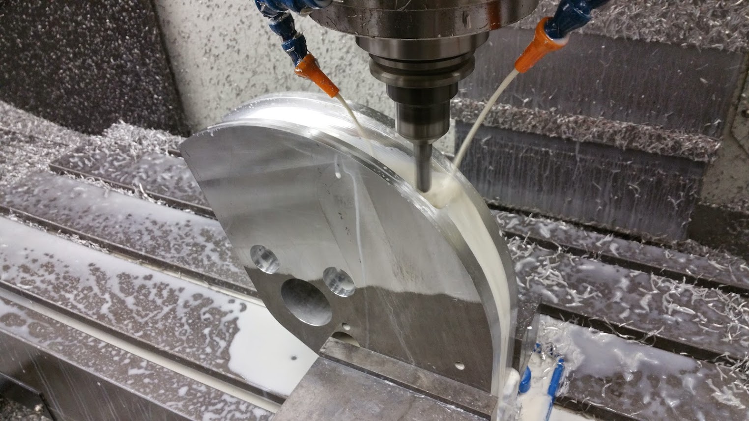
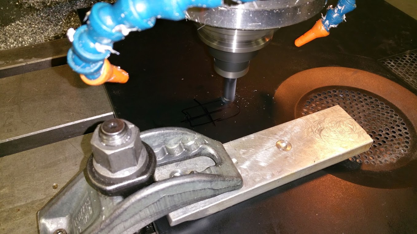
The first step was to cut the the blank die out of 2.5 inch aluminum. Next we clamped it in a vice on the mill and used a radius tool to cut the tube profile. Instead of putting the die on a rotary table, we just cut it in two setups. Here it is getting the first portion of the profile machined.

die profile machining

After machining the other half, we bolted it to the pieces we installed earlier.

die bolted onto the bender

You can see four holes on the die that have been tapped. Part of the latching mechanism bolts here. I did not get any photos of us machining that piece but in a later image you can see what it looks like.

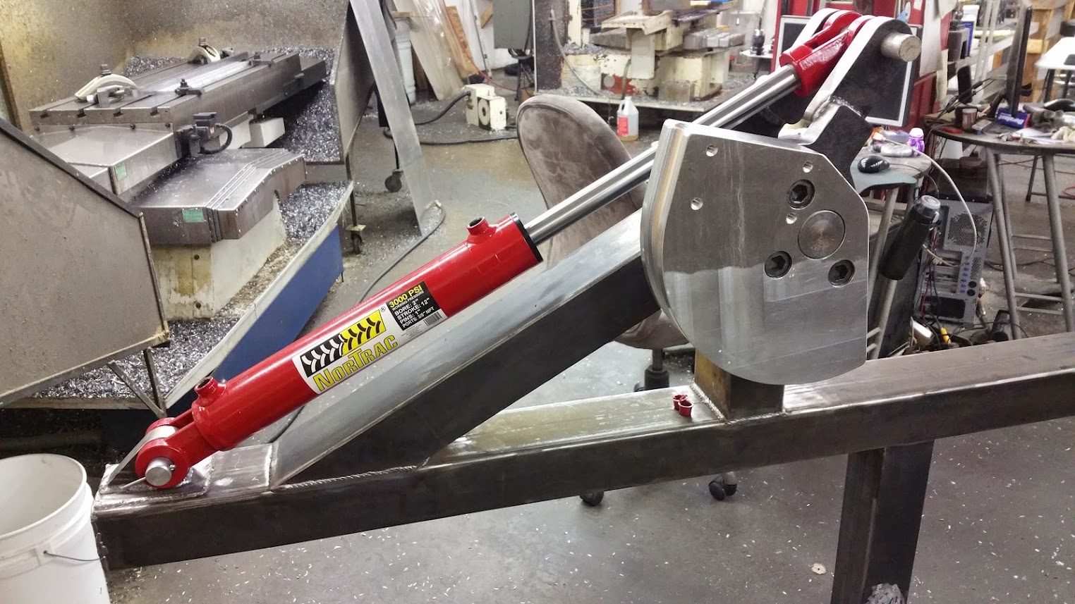
Next we moved on to making the parts that would raise and lower the pressure die (long straight die that the tube rests in) to hold the tube against the bending die. These components are located under the yellow pieces in the following image:

pressure die mechanism

During normal operation, the pressure die is down while the tube is being fed. When the tube gets in place, the pressure die lifts and pushes the tube against the bend die. As the tube is bent, the pressure die stays with the tube, sliding beneath the bend die. When the bend is complete, the pressure die is lowered and slides back to its starting position while the tube is fed to its next bend location or is removed.

feed the tube >> raise the pressure die >> bend >> lower and return the pressure die >> repeat

I did not get photos of the first piece we made of the pressure die lifting mechanism. I know, I'm terrible. This piece is the one the pressure die sits in and slides on. It has a threaded section to attach the hydraulic ram, two bolts to set the lift height, a shallow slot for the pressure die to slide in and a small pocket to hold an oiling roller.

We machined and welded this piece and used it to position the plates to make the mount that would hold the lifting assembly to the bender frame. Then we welded the mount together and set it out in the snow to cool off.

clamping the mounting assembly to weld

triangles welded to the mounting plate

mount welded together in the snow

Then we test fit the lifting assembly to the frame of the bender. You can see the latch piece I mentioned earlier bolted to the die.

bender with lifting assembly clamped

JThw8
JThw8 PowerDork
4/20/15 10:24 a.m.

amazing work, thanks for letting us follow along

Bearded.Bird
Bearded.Bird Reader
4/20/15 10:51 a.m.

Man you guys are awesome. Keep this up. I may learn a thing or two.

adoyle88
adoyle88 New Reader
4/29/15 3:42 p.m.

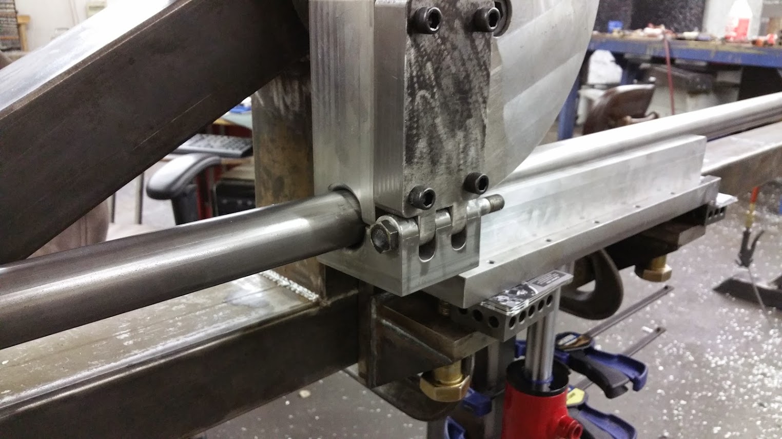
Next up on the bender was the other half of the latch that holds the tube to the bending die.

hinged latch piece

It took a few different setups to machine all of the features of the latch. Here it is temporarily attached using a random bolt as a hinge pin.

latch temporarily assembled

In the next pic you can see where we latched around a tube. The swinging portion of the latch gets a short arm welded to it that connects to the latching ram. As the ram extends, it closes the latch and holds it closed until after the bend is complete and the machine is ready to feed the tube to the next position.

latched on a tube

To finish up the mechanical portion of the latch assembly, we machined out steel supports for the ram and welded them to the portion of the latch that is bolted to the bending die. The ram screws into a pivoting piece mounted between the two supports. In the photo below, you can see the latching ram installed and connected to the arm of the pivoting latch piece.

latching ram installed

We manually moved the bender to a few positions and took a series of photos so that google could animate them:

bender animated

RossD
RossD PowerDork
4/29/15 3:49 p.m.

Very cool!

morecowbell
morecowbell New Reader
4/30/15 9:37 p.m.

Very nicely done!

adoyle88
adoyle88 New Reader
5/7/15 12:04 p.m.

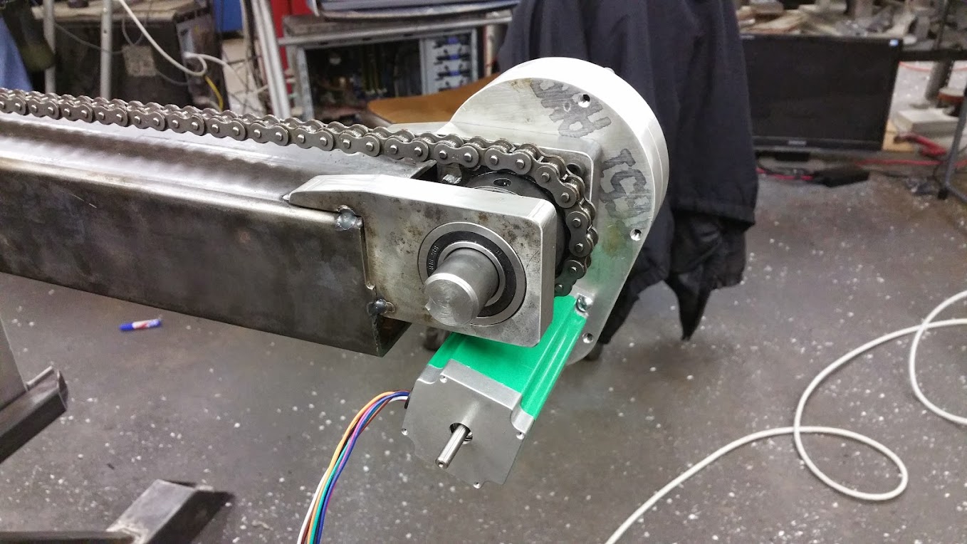
The chain that feeds the tube through the machine is driven by a 420 oz-in stepper motor through a homemade gearbox. Testing it out, we measured the max feed rate at 250 inches per minute with our current gearbox.

stepper motor, gearbox and chain

Near the bending assembly, the chain wraps around a sprocket and returns to the back inside of the main square tube.

chain going back into the bender

The CNC equipment we decided to use is from a family owned company called Probotix. We purchased their 2 axis Monster CNC kit. Probotix was very helpful when it came time to figure out how to drive the hydraulic switches, directing us to their custom relay board.

We gathered up computer parts from a few of our old computers and assembled a control station for the bender. We removed the CD tray and hard drive mounting box from the old tower and installed a piece of acrylic to mount all of the CNC equipment all in the tower for a clean setup. In the following picture you can see (starting from the foreground) the relay board, breakout board, stepper driver and stepper power supply installed in the tower. The hard drive is mounted to the underside of the acrylic.

bender control station tower

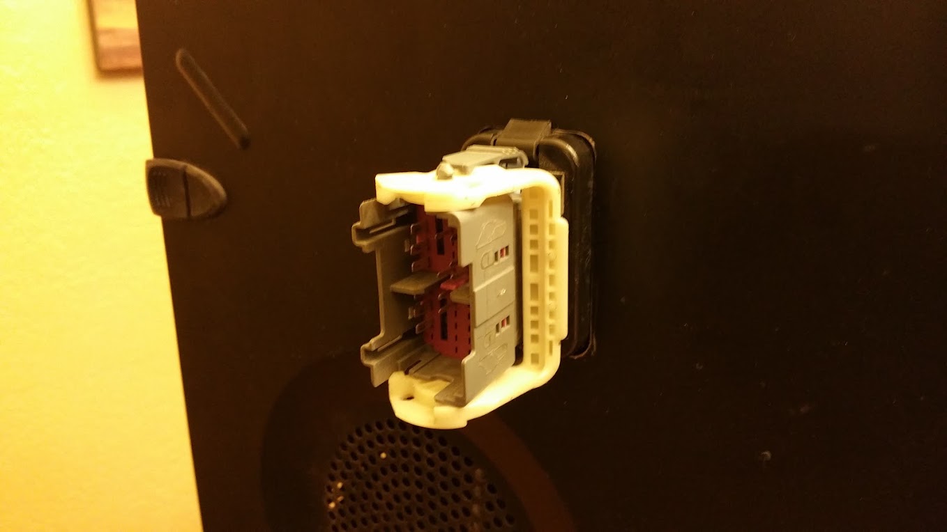
To get all of the CNC wiring out of the tower, we decided to reuse some wiring from our Goblin donor. We used the plug that goes to the driver's door.

plug for the side of the computer

First we cut a hole in the side of the computer case.

hole in side of the case

Then we popped the fixed portion of the plug into the sheet metal of the case.

plug popped in

And finally we plugged in the pig tail that will eventually be spliced to wires coming from the bender.

pigtail in the computer

adoyle88
adoyle88 New Reader
5/12/15 8:08 a.m.

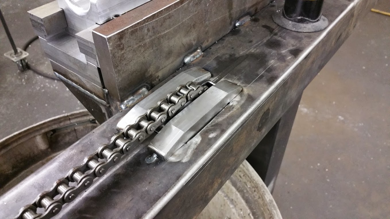
To feed the tubing, we are using a little chain driven platform that we call the tractor. We have limit switches in place to stop motion if the tractor ever gets to the extreme ends of the machine. To add a little bit more security in case anything goes haywire, we connected the tractor to the chain with a plastic piece so that hopefully it will break away before anything else breaks.

plastic tractor-chain connector

The plastic connector snaps into the chain and bolts thread into the plastic to hold it to the tractor.

tractor connected to chain

We worked on a few different mechanisms that could lock the tubing to the tractor during feeding and then release the tubing during bending. This way, the tube can be fed into position by the chain and then be pulled freely by the bending head without us having to synchronize the tractor movement with the bending ram. I didn't get images during fabrication of the final design but you can see a shot of it later in this post.

With a stepper motor, it is easy to move a certain distance by knowing how many steps it takes to move an inch. Then it comes down to sending the correct number of impulses to the motor. However, the hydraulic ram we are using on the bend axis is either moving or not moving and can travel a variable distance while moving depending on the strength of the tube, the temperature of the hyrdaulic fluid and many other factors. This means that we can't control the ram from the computer without getting some feedback.

To get this feedback, we decided we would use an optical encoder to measure the location of the bending axis. The encoder we made is composed of two photo interrupter sensors and a slotted wheel. We cut really fine slots in the wheel to achieve a .25 degree resolution.

optical encoder

As the bend axis moves, the slotted wheel rotates through the sensors. The pulses are counted by the computer and converted to degrees traveled. We manually whipped the bend axis back and forth as fast as we could and the encoder never missed a beat.

I know you guys are getting tired of me saying this, but I once again failed to take photos. In the next photo you can see that a lot was completed:

lots of stuff completed

First thing you probably noticed is the dozen or so hydraulic hoses. We bought about 50 feet of hose, cut them to the lengths we needed and then had a local shop crimp the ends on.

We also installed the two solenoid operated hydraulic valves. One is a two position valve that opens and closes the latch mechanism. The other valve has three positions that extend, retract or hold the bend ram.

Toward the right you can see the tractor. The tube pushes in between a bearing on top and a one way clutch bearing on bottom.

On the far right you can see the tank, pump and pump motor. Here is a better shot of those:

pump and tank

The motor puts up 5hp at 1750 RPM. We consulted with a local hydraulics shop when selecting the pump. The pump has to continuously keep pressure to hold the rams, so we had to go with a more sophisticated pump than we had planned. Our first one got very hot just being switched on.

After getting everything hooked up, we did our first test bend using the computer to manually feed and bend to arbitrary numbers:

first bent piece

It bent it without struggle and the bends look better than any we ever did on our old hydraulic bender.

RossD
RossD PowerDork
5/12/15 8:34 a.m.

Awesome! I love projects like this!

DILYSI Dave
DILYSI Dave MegaDork
5/12/15 9:06 a.m.

Very Nice!!!

adoyle88
adoyle88 New Reader
5/14/15 11:59 a.m.

The moment everybody has been waiting for: Video of the CNC bender in action

Not the most exciting video in the world, but the frame rail that was bent in the video dropped right into our chassis jig. It also had way prettier bends than what we ever achieved on the old bender.

Now, let's wrap up the build:

After our test bend, we finished up the 1.25 inch side of the bender before disassembling the whole thing for paint.

bender ready for paint

As you can see in the video, we opted for a nice vibrant blue with bright yellow accents. After several rattle cans, the frame and other pieces were coated.

bender painted blue

pieces painted yellow

Then it was just a matter of assembling it all:

stepper, chain and limit switch

pump, motor and tank

bend ram

latching ram

pretty much finished

Next up on our equipment/tooling to-do list is the tubing notchers.

Cleverfrog
Cleverfrog Reader
5/14/15 12:05 p.m.

such amaze

Flight Service
Flight Service MegaDork
5/14/15 12:17 p.m.

sweet

bgkast
bgkast GRM+ Memberand UltraDork
5/14/15 12:43 p.m.

Slick! I like how the lower die moves with the tube rather than having the tube move across it and getting greasy and/or scratched up. How to you move the lower die back into position to set up for the next bend?

adoyle88
adoyle88 New Reader
5/14/15 1:28 p.m.

I skipped over how the pressure die returns. Since it is clamped against the tube as the bend ram extends, it gets pulled along. As soon as the bend is finished, the pressure die is retracted and is free from the tube. We could have used a spring to bring the die back, but that would have been pretty violent. Instead, we used a gas strut like the ones that hold up a car hood.

gas strut hooked to pressure die

Using this, the die returns in a controlled manner. You can see that we still haven't installed one on the 1.25 inch side of the bender. We haven't attached the tractor clutch mechanism for that side either.

bgkast
bgkast GRM+ Memberand UltraDork
5/14/15 1:35 p.m.

Very cool. I know who I'm calling next time I need a hoop bent up.

Bearded.Bird
Bearded.Bird Reader
5/14/15 2:53 p.m.

Berkleying sweet. You guys are amazing.

1 2

You'll need to log in to post.

Our Preferred Partners
HeGlmZKTkimUrTK2KhS5OG7Bu3Ok0zA2DLmQKRJyXSSVtKBmQwRZsYb1SpcM5Wr4