Hi everybody, here is a somewhat nerdy project I have been working on instead of fixing on the Mazda. If you like robots, gizmos and cameras then pull up a chair and have a look.
Just a quick reminder, I have changed my user name from Fujioko to El Cheapo and then to Doc Brown.
Anyway, the goal is to build a automatic tracking camera for multiple purposes. As the story unfolds you will likely see some interesting things and of course some bad demonstration videos.
Let's begin...
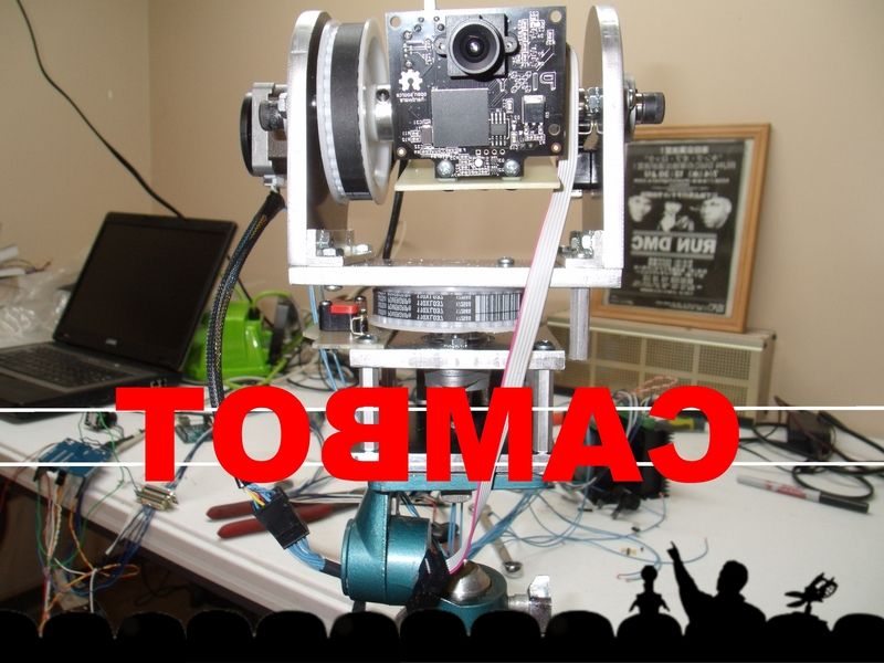 Robot roll call........... CAMBOT!
More in just a moment!
Gypsy! Tom Servo! Crooooow! 
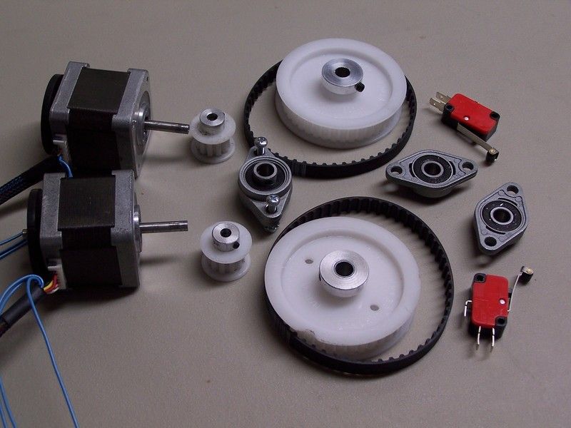 After much thought and a few sketches the scavenger hunt began. The parts needed for Cambot were sourced from McMaster Carr, Ebay and Amazon.
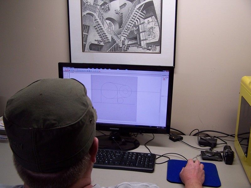 A few evenings were spent drawing up the components that needed to be fabricated. I used a free software package that wasn't really meant for drawing parts but it can be tricked into doing what I want.
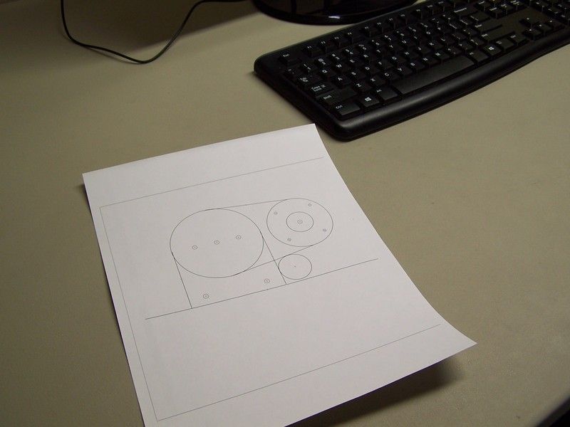 Once drawn, the parts can be printed out on a 1:1 scale. ... ummm yeah, printed on paper. I ain't got a 3D printer....yet.
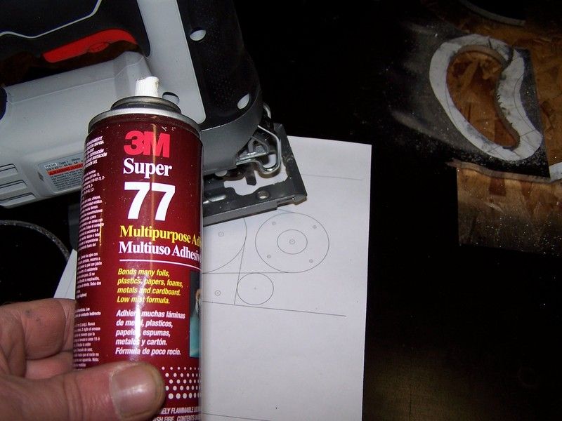 The 1:1 paper drawing is glued to a slab of aluminum and then cut out with a saber saw. This is not exactly high tech but it works great.
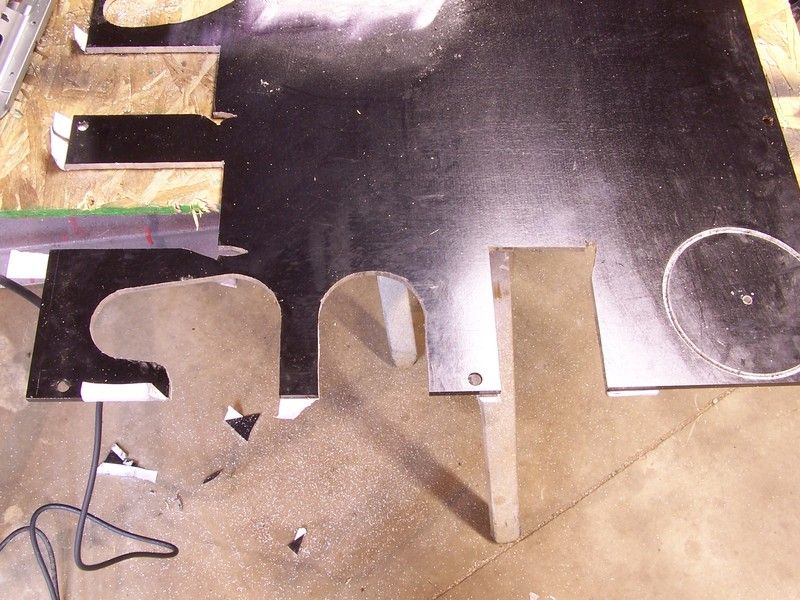 It was a bit tricky, but I managed to cut out all the components needed in only a few hours.
Stay tuned!
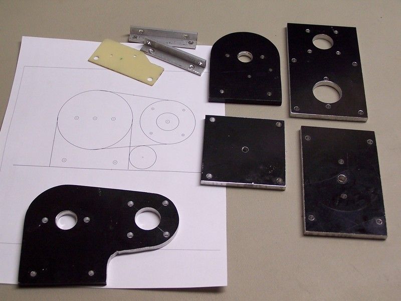 Once all the parts were fabricated it was time to start assembly.
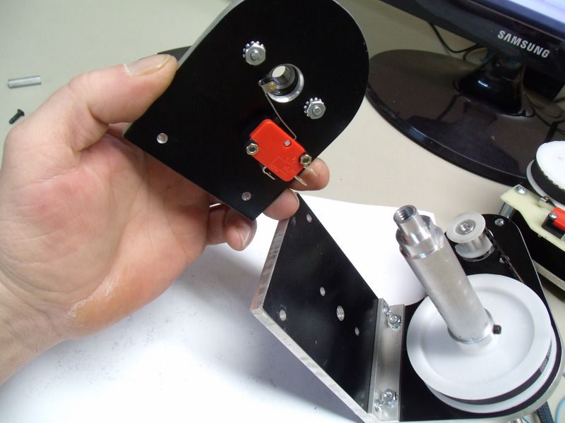
 First up is the pan section. This part of Cambot will allow the camera to swing left to right. A stepper motor and a set of turret bearings are mounted to one of the fabricated aluminum panels. The aluminum is .25 thick and is overkill but it was all I had in stock. Version 2.0 will likely be made from fiberglass.
 Another chunk of aluminum is attached to the pan section with 8-32 standoffs. This smaller section is the base of Cambot and has a standard 1/4-20 threaded camera mount.
 A limit switch is attached to the pan section. This switch will be monitored by the software and is used to calibrate the extreme left position of the camera pan. Once the switch it tripped, the micro computer knows exactly where the camera is pointing. The software can now keep track of the steps commands that are sent to the stepper motor. The magic of digital electronics
More in a moment!

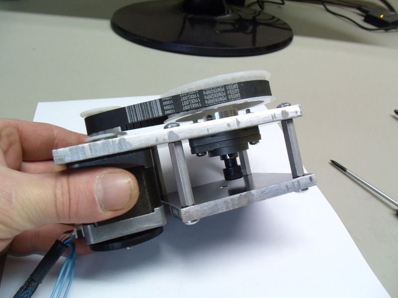
 With the pan section more or less complete, its time to assemble the tilt section. The tilt section was designed to be easily modified to accept different cameras for different rolls. The little Pixy camera at the beginning of this thread is a specialty camera and isn't used for video, instead it is a color tracking camera that can sort out the position of objects and send a serial message to a micro computer. The micro computer uses this information and will calculate the X-Y position for the pan and tilt. Its a fascinating chunk of technology.
Anyway, the Pixy cam is use to track an object, another camera will be used to record the object in high definition. Its actually a bit more complicated then I wish to explain and eventually a few hurdles need to be jumped to make this work in the real world.
Back to assembly....
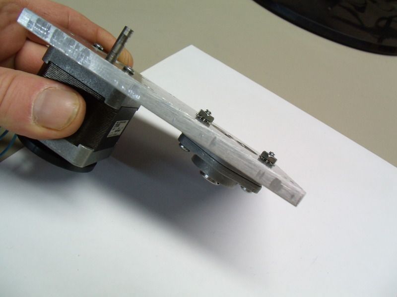
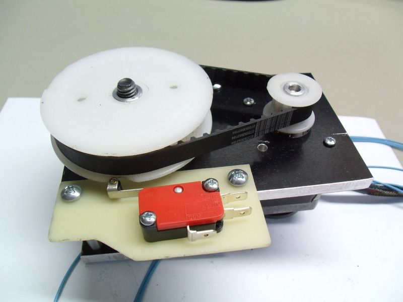
The tilt section build starts off with assembling the left motor plate. A stepper motor, bearing and toothed cog are fastened together with 6-32 screws. The aluminum shaft protruding from the assembly is part of the universal mounting system.
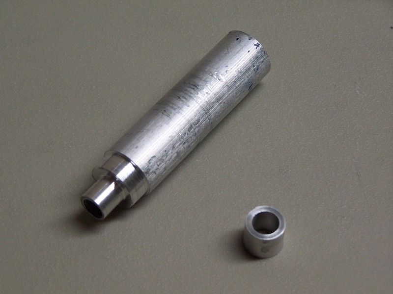 here is a close up shot of the aluminum shaft and a spacer. These parts were made on a lathe using some scrap.
 The left motor plate was mounted to a base plate before the right support plate is introduced into the mechanical orgy.
Note.. the right support plate has a limit switch to telegraph the position of extreme downward tilt.
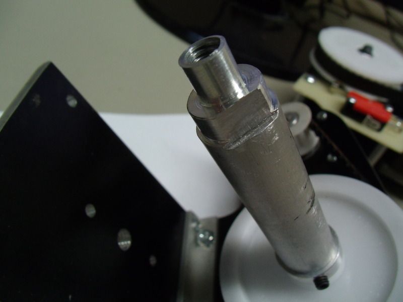 Here is a close up shot of a notch filed into the aluminum shaft. This notch acts like a cam and is what triggers the limit switch.
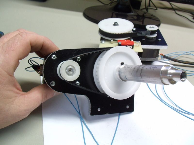
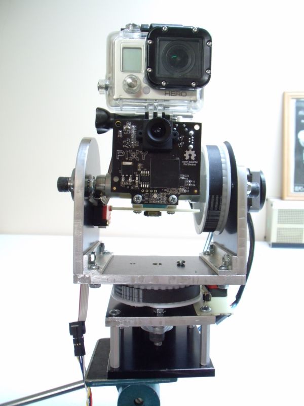
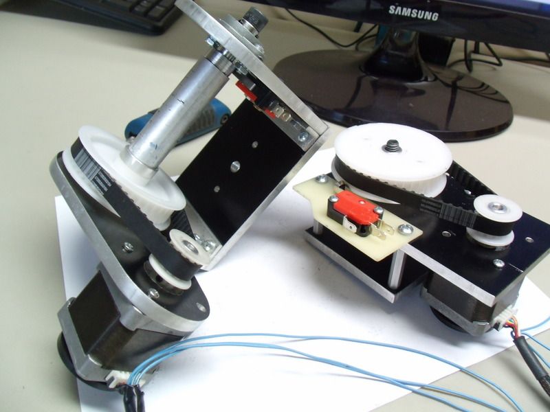 The finished tilt section ready to be mated to the pan section.
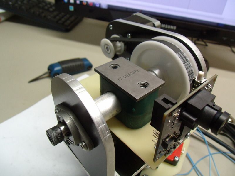 Here is a close up shot of how the Pixy camera is attached to the tilt shaft. The green plastic thingy is a split clamp and is the heart of the universal mounting system. All modification can be made to the cheap plastic clamp and saves a bunch of time and money for different experiments.
Stay tuned!
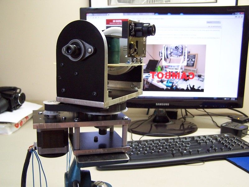 Cambot assembled and mounted to a vintage tripod. Somewhat of an interesting photo.
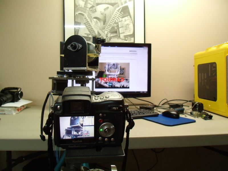 Picture of Cambot being photographed while simultaneously appearing on the Internet in its own build thread. Just because its possible, doesn't mean it should be done..... but I did anyway.
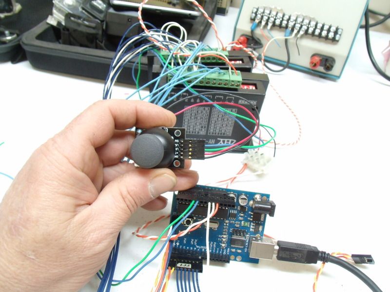
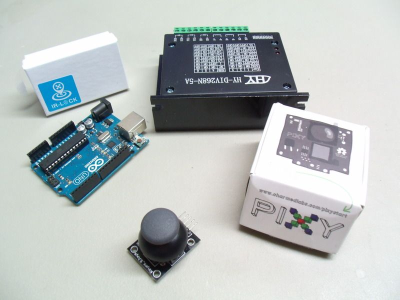 Alright, let's take a look at some hardware.
Lower front is a miniature joystick for manual control. The joystick is a necessary feature to override the automatic tracking software.
Over on the middle left is an Arduino UNO. This little micro is has plenty of resources for developing this project but ultimately it will be replaced with a Mega. The Mega series has some additional serial ports that will be necessary when project creep inevitably rears its ugly face.
Top middle is one of two stepper motor controllers that are used for this project. These controllers are used by hobbyist CNC builders and more or less have a bad reputation. Most complaints are these controllers do not supply the advertised power. Meh, they should be fine for this project. Another complaint is the dip switch silkscreen it completely wrong. The good news is these controllers can be picked up for less than a twenty dollar bill.
Over on the right is of course the Pixy camera.
Top left is a filter kit used to modify the Pixy for inf-red capture. The kit will give the Pixy the ability to track objects up to 60 feet away.
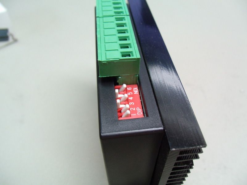 Here is a shot of the dip switch settings that seem to work.
Stay tuned!
This build is way cool, although way over my head I do enjoy reading about the fabrication. I also have that M.C. Escher drawing - mine was a puzzle that we framed.
In reply to EastCoastMojo:
Thanks!
A lot of build threads are way over my head. Especially when the topic is about suspensions.... but I love to look at the pictures of the fabrication process. .
Anyway, posting such an unusual project keeps me motivated and hopefully it wont fall into the Jimmy Hoffa bottomless pit of dead projects.
I'm wondering how it eats and breathes, and other science facts.
In reply to Acme Lab Rat:
Just repeat to yourself, it's just a build thread, I should really just relax....
So what's the detection range on this? It could be an interesting security camera - track and follow objects, then reset to a neutral position.
In reply to Acme Lab Rat:
Good question,
The Pixy camera is trained to detect an objects color at close range. In a well lit room the camera has a range of 4 - 6 feet. The IR-lock kit modifies the camera to track an IR beacon from 15-30 feet. Ideally you would want a camera using FLIR technology for tracking humans / animals for security purposes.
I envision several purposes for Cambot, primarily it will be used as a platform for a high definition camera to record unique video shots. I also want to develop proprietary software for domestic robot use.
To get a better idea of what Cambot primary goal is, take a look at Soloshot.
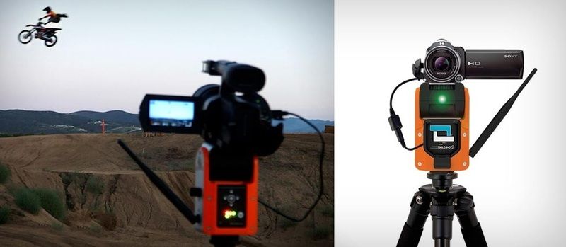 Soloshot and Cambot are close relatives.
Photobucket is acting up again.... today's post will be relatively brief. Actually... someday when my robots take over the world, the first thing I'll do is to send a team of tech commandos over to photobucket and get E36 M3 sorted out. This is unbelievable
 Finally the picture is available... nothing exceptional, just a rats nest of wires. Anyway this is the basic wiring for Cambot. It looks pretty bad, but I assure you its just as bad as it looks. Perhaps a schematic would be better..
 For the nerds, here is a schematic for basic operations via joystick. Understanding how the joystick is used to control pan and tilt is the first step for automatic operation. I'll update this thread with the Pixy schematic and code in the near future.
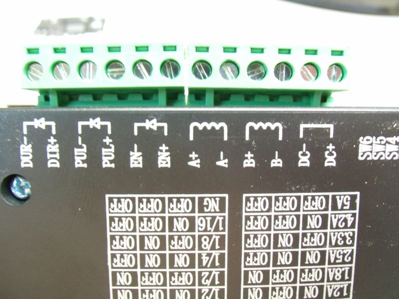 Just a close up shot of the stepper controller that is referenced in the schematic.
Here is a github link for simple joystick code to control the pan and tilt..
Code for simple pan and tilt
We got movie sign!!!!
https://www.youtube.com/embed/1y01CJpBQ1U
Stay tuned!
I halfway expected the robot on the counter to light up like they were communicating at the end of the video.
Very cool project. I have a bad tendency to let the magic smoke out of things like that.
In reply to EastCoastMojo:
sooon....
In reply to Toyman01:
Thanks!
I blow E36 M3 up at work all the time, however I'm real careful with my own projects.

RossD
UltimaDork
1/18/16 7:38 a.m.
I love your projects! Great work!
In reply to RossD:
Thanks Ross! Having fun and staying warm this winter.
Quick update..
Fooled around with some software and got some pretty amazing results. Its not perfect but a good start.
The pixy camera was modified with a filter and lens to detect infrared light. The filter kit improves long and short range tracking, however it also obscures any video image generated by the Pixy. I wasn't really interested in the Pixy's video feed so this it not even an issue.
Cambot, Pixy and GoPro... this is going to get interesting.....
We got movie sign!!!!!
https://www.youtube.com/embed/hrXLw0CeGaw
Stay tuned!
RossD
UltimaDork
1/19/16 7:17 a.m.
Is programming for hysteresis easy? In my head the logic is relatively simple, but...
In reply to RossD:
Wow, thats a tough question to answer. The short answer is writing code to minimize hysteresis can get very complicated depending on application.
In the second video some of the twitching is due to the whole tripod vibrating when the stepper motors apply torque to the pan and tilt.. The torque pulses that are carried through the tripod cause minor errors in the Pixy camera position and the system will over correct. I have toned down the problem with simple tweaks but a lot more code is needed. The problem seems to go away when the object is further away from the camera.
RossD
UltimaDork
1/20/16 9:51 a.m.
In reply to Doc Brown:
With the object being farther away and the problem being lessened, I'd guess that you have a maximum degree/sec before starting to get the tripod vibrating. You could add mass to the tripod; an old dumbbell solidly mounted perhaps. Or have a 'soft start' to the pan motor.
Cool Build. Looks like I need to change my screen name... again. Sorry about that origional Doc Brown.


