1 2 3 4
TheTick58
TheTick58 GRM+ Memberand New Reader
12/31/20 1:16 p.m.

Well, me for one!  (Spoiler alert) This is a project I've been working on for about 2 years now, and managed to get it on the road a couple months ago.  I've been keeping a build thread of sorts going on my local autocross forum, but that thread has a lot of... let's call it "local color" and inside jokes from the other locals.  I have been thinking I should move the actual build details somewhere else to make it more "build specific".

So, here I am!  My intention with this project was to have a fun and faster Miata that had OEM reliability.  Sure there are turbo kits out there that can make plenty of HP, but I wanted to be able to turn the key and not sweat whether the car was going to bring me home at the end of the day.  The 2.0 EcoBoost motor makes 240-250hp and 270lbft torque stock.  With the "Controls kit" from Ford Performance Produces, teh tune brings that to 270hp, and 350 lbft.  I figure that will be more than I'll ever "need", and likely more than I'll ever be able to use, while still being stone reliable.

 So keep in mind this is a project that has 2 years in it already, so many of the "issues" discussed have been resolved already, but I'm always interested in hearing other ideas!

Just to help with some of the jokes that are tied into this whole thing...  I'm, well, OK, I'm cheap.  I've been autocrossing for many years, and one of my autocross friends dubbed my garage as "World head quarters of Frugal Racing Enterprises".  This resulted in all of my competition endeavors being under the banner of "F.R.E. Racing" with the catch phrase "It's not FREe, but it's close".  So when you see references to "Free with BOTH E's", that's what I'm refering to....

TheTick58
TheTick58 GRM+ Memberand New Reader
12/31/20 1:25 p.m.

(12-18-2018); Everyone loves a Miata am I right? What is it that the Miata is missing that should make it an even better...Miata? Yeah, more power.

A few years I heard that a 2.0 ltr EcoBoost motor (think Focus ST) would bolt up to an NC Miata transmission. That and Ford Performance had a kit that would operate the motor as a complete stand alone (connect a ground, a power, and a couple control switches and it's good to go). I started talking about this being a great answer for a Miata. A fun daily driver/occasional track day toy sort of thing. I've kicked this idea around for a few years now, so it was finally time for me to either shut up (not all that likely in reality), or do something about it.

So here we are at the early stages of the "F.R.E.coboost Miata", or maybe "Menschenstien II" (carry over from my motorcycle days), or "insert something clever here".

The biggest issue on this project is I'm cheap...er...frugal.

So I found a rust free 99 Miata with a bad motor (and a rollbar, 15x7 wheels and coilovers) for a pretty good price, so I was off to a good start.

The first problem was Ford Performance doesn't sell the kit anymore... Luckily I found a tech at FPP that was willing to program an ECU that I supplied (free with both "E"s! other than having to buy an ECU). I also found someone at FPP who was willing to send me the wiring diagram for the chassis side harness that goes along with the ECU programming, so I could build my own. Not free, but definitely FRE!

The next problem is a scrap yard Focus ST motor can run $1500-2000, but... last week I picked up a 2.0 ltr EcoBoost motor from a 2014 Ford Fusion (74k mile, 240hp) complete down to the accessory belt for $324. The Fusion motor uses the same turbo, cams, pistons and head, so I assume the biggest difference (and the cause of the 12 fewer hp) is ECU programming, and I already have that addressed with the FPP ECU.

This is certainly just the start of many "adventures" related to making this mismatched bunch of parts into an operating vehicle, but I'm started down the road. I don't have a real timetable (other than hoping I can drive the car this coming Summer). It's not being built to fit into any particular race class (though I hope to keep in SSM autocross legal), it will mostly be a fun street car/occasional track day (TNiA) toy. Oh, and I'm hoping to be able to keep the whole budget under $5000.

Wish me luck!

TheTick58
TheTick58 GRM+ Memberand New Reader
12/31/20 1:40 p.m.

(12-27-2018); 

As of now the plan calls for parts from 7 models (2 brands);
a 1999 Mazda Miata chassis
a 2014 Ford Fusion Motor
a 2006 Mazda Miata Transmission
a 2013 Ford Exploder ECU (reprogramed by FPP)
a 2013 Ford Focus ST engine harness and accel pedal (fly-by-wire)
a 2004 Ford Ranger 2.3lt Oil pan (bolts right up to the 2.0 EcoBoost motor)
a 2016 Ford Mustang intake manifold, coolant pipe

These aren't exactly "from a different car", but they aren't from the 99 Miata either;
handmade chassis harness (copy of the FFP kit part that isn't available any longer)
an NA Miata (aftermarket) aftercooler (does that count as another car model?)

I'll update this list as the project moves along and other "solutions" are found.  There have been suggestions that there might be a tie in to an old Jonny Cash song, but I've resited so far.

TheTick58
TheTick58 GRM+ Memberand New Reader
12/31/20 1:48 p.m.

(1-13-2019)

So it have about a month since I started tinkering with this, so I thought I'd post a little update. My "Garage time" has been limited a bit by the weather (I live in Minnesota), but not as bad as it could have been

I have a small 2 car garage, one side of which I don't get to use for more than daylight hours (my wife's car always gets to park inside at night, those are the rules). The other side of the garage has, well, everything else I have (plasma cutter, MIG welder, torch, air compressor, tire machine, engine hoist, 2.0 EcoBoost, 2 Miata motors, CRX Spare motor etc) and it's not insulated, so, well, it can be a challenge.

Anyway, since I last posted up I've bought a second front subframe for the Miata so I can modify and/or build motor mounts outside of the car. I bought the last known "Orientation kit" that FPP had to fit the FWD EcoBoost into a RWD platform (turns out to be mostly a collection of 2016 Mustang parts), and an NC 6 spd transmission.

After doing some looking/measuring/scheming I decided that the 2016 Mustang oil pan that came with the Orientation kit just wasn't going to be the best solution. The EcoBoost motors have a Counter Balancer Shaft(s) that live under the crankshaft. The Mustang oil pan has enough room to allow this to stay in place (and as a result forces the motor to be taller above the subframe). The EcoBoost block is based on the same block as the 2.3 ltr Ford Ranger motor (as well as the 2.5 ltr motor in other assorted Ford and Mazda vehicles). The Ranger motor doesn't have the counter balancer shaft, so I picked up a used Ranger oil pan and an aftermarket "balancer shaft delete kit". Preliminary test fitting looks like it will save me about 2" of height (important detail with the Miata hoodline), and it bolts right up! Eliminating the balance shaft doesn't scare me too much, it was added to the motor line sometime on the early 2010's to help quiet down the "secondary" vibrations, so it may make the car a little more buzzy, but the primary balance is still correct with the crank etc, so I'm OK with that (and members of the motor family has been as big 2.5 ltrs without the shaft, so I'll take comfort in that as well).

I also built up the relay/fuse box (based on the FPP diagram), so I have that ready to go.

The high pressure fuel line is the most rearward portion of the motor when in a RWD configuration, and if the motor is in the same place as the Miata motor the fuel line will need to go an inch or so into the sheetmetal in the back of the engine compartment. I've considered making a new fuel line with a tighter bend coming out of the HP Fuel Pump (it's on the back of the intake cam, about where the Miata coil packs would be, and the fittign points straight back), but Ford used some nonstandard fittings that I can't identify, and, well, it's a 2000 PSI fuel line, so I'd want to have it right... So the current plan is to cut into the back of the engine compartment to make room. Luckily it's high enough that it will only be into the space in front of the windshield where the wipers live, and I think everything will be above the actual "firewall", so I won't have to cut a hole into the "people space".

So, some planning done, some wiring done, some more measuring done, some parts swapping done. Soon I'm hoping to do some subframe mock up to see how that's going to work out. I have an idea of how the motor mounts will need to be made, and where they can catch the subframe, so I'll look into that next.

RossD
RossD MegaDork
12/31/20 1:55 p.m.

I like this!

TheTick58
TheTick58 GRM+ Memberand New Reader
12/31/20 1:59 p.m.

(1-18-2019)

Another quick update;

I'm using a complete and stock 2013 Focus ST engine wiring harness, and this harness has a nice 41 pin plug that connects the motor harness to the chassis. I thought this was a pretty nice piece as well as making pulling the motor pretty easy, so I wanted to keep it. The problem was I couldn't get any of the on-line parts places to give me a straight answer to my inquiries looking for the chassis side connector to use for the wiring I need to add.

Well, as it turns out, the connector is part of the engine bay fuse box, so at least that explains the confusion... I found a number of these available at $125-150 (a lot when I'm just going to chop it up to salvage a single connector). I finally found one in Moundsview for $25 (thank you car-part.com)! 20 minutes after getting it home I had the connector "unclipped" from the fuse box and moved a few of the pins to get the configuration I needed! So we got that taken care of.

On the motor mount front I wanted something that had an OEM type rubber isolation (this is a street car after all), but really wanted something that was; 1) relatively thin and flat, and 2) would use a "saddle/tube" (by that I mean one side will have 2 "tabs" some distance apart, while the other side has a piece of tubing that will fit between the tabs. Then a bolt passes through both) type of connection to make fabrication easier. Also needs to be able to support the motor weight and deal with 250ish HP. Doing a little surfing I found that 1st gen Camaro motor mounts look to fit all my requirements! They are fairly thin, have a mounting system I can use, should be able to put up with both the weight and the output of my motor.  If I want to "upgrade" later there are lots of aftermarket options that fit this application, and (here's one of my favorite parts) they are CHEAP (like $11 each)! So I got that going for me.

More later.

TheTick58
TheTick58 GRM+ Memberand New Reader
12/31/20 2:04 p.m.

(2-03-2019)

Another couple weeks later and...

I did get the Ranger oil pan on, and it's the right answer considering the room I have.  In one of the pictures below you can see the 2 oil pans.  In the photo the Fusion pan in on top, the Ranger pan on the bottom. While the Fusion sump looks huge, keep in mind that I have removed the twin shaft counter balancer that used to live in the front (right in the photo) of the Fusion pan. I'll try to get a pic of the balancer and the pan together, but it's about as wide as the pan, and about half as long as the sump (and weighs 19 lbs!). I've read comments that deleting the balancer and using the stock oil pan requires 2-3 quarts more oil.

I was a little worried I might need a windage tray with the Ranger pan, but the sump is fairly small, and close to the pick up, so I'm planning to run it as it is.

On to the subframe. I bought a second front subframe so I had something I could carve up outside of the car (and so the car could still sit on it's wheels), so I dug right in. With the Ranger oil pan the subframe is about 1/4-1/2" too tall to get the crank height I need, and the back of the "U" portion of the subframe interferes with the oil pan sump.

Did I mention that I have a plasma cutter?

So after some quality plasma cutter time, I think I have room now. I need to pick up some rectangle tubing to patch the subframe back up to snuff, but it's looking good so far!

Next up? Well, next up is a trip to Cozumel! I'll look at the car more once I get back from there.

P.S. The plasma cutter is becoming my new favorite tool....

TheTick58
TheTick58 GRM+ Memberand New Reader
12/31/20 2:08 p.m.

(3-2-2019)

With the current weather I haven't done a lot, but I have decided to not try to mount the Miata power steering pump to the EcoBoost motor and instead I'm planning to add electric power steering.

I was originally looking at using the electric powered hydraulic power steering pump from an MR2, but being the cheap guy I am...

I have already picked up the parts for this (power steering unit from a Saturn Vue, and the controller from epowersteering.com). It also looks like I'll need to lower the steering rack due to oil pan clearance (or rather lack of), so I also picked up the Vue steering rack. It's quite a bit smaller in dia than the Miata power rack, so I won't have to move it as far.

That's about the only updates so far (oh, Mexico was warm, and I didn't have to shovel any snow...). Hoping the weather warms up soon and I'll be able to get some of this work done!

Also an update to the "Where did all these parts come from" list;

As of now the plan calls for parts from 10 models (4 brands);
a 1999 Mazda Miata (chassis)
a 2004 MazdaSpeed Miata (aftercooler and seats)
a 2006 Mazda Miata (Transmission)
a 2014 Ford Fusion (Motor)
a 2013 Ford Exploder (ECU)
a 2013 Ford Focus ST (engine harness and accel pedal (fly-by-wire))
a 2004 Ford Ranger (Oil pan)
a 2016 Ford Mustang (intake manifold, coolant pipe)
a 1968 Chevy Camaro (motor mounts)
a 2007 Saturn Vue (power steering unit and steering rack)

Dusterbd13-michael (Forum Supporter)
Dusterbd13-michael (Forum Supporter) MegaDork
12/31/20 2:15 p.m.

Watching!

TheTick58
TheTick58 GRM+ Memberand New Reader
12/31/20 2:18 p.m.

(3-27-2019)

Another small update. With the nice weather I played hooky today and played in the garage instead of going to work!

The EcoBoost motor is a bit taller than the Miata motor. I'm hoping to be able to not alter the hood, so in order to make everything fit I needed to alter the front subframe (see pics in earlier post). Today I made final decisions on the subframe mods and welded the reinforcements in to make it whole once again. It's a little heavier then how it started out, but I think it should be sturdy enough.  There are tubular subframes available out there, V8Roadsters makes a nice one, but that just doesn't fit into the whole FRE scheme of things, and hey, I HAVE a plasma cutter...!

I also think the motor will be low enough to be able to get the stock hood closed without a "hood scoop/power bump". I might have to alter/remove some of the cross bracing on the hood, but we'll fall off that bridge if I mis calculated.

So, that's about it for now. Next step is going to be test fitting the subframe and the motor/trans to see if I got my measurements right. That will lead to cutting into some of the sheet metal in the engine compartment to make room for the high pressure fuel line, not my favorite part, but the first alteration that I won't be able to easily undo...

Anyway, have plasma cutter, will travel!

TheTick58
TheTick58 GRM+ Memberand New Reader
12/31/20 2:28 p.m.

(6-11-2019)

So, It's been a while, and while the weather has definitely improved, but my health hasn't. I've had a case of the crud for going on 4 weeks now... Cough, headache, chest congestion, you get the idea. Not ideal garage motivation.

Since our last installment fine readers the bottom of the motor is buttoned up. I did go with the Ranger oil pan, and in an attempt to make that easier I picked up a Ranger oil pick up tube as well. That came close to working. I had to "massage" it a little to get everything to line up as it should, but in the end it was a good solution (didn't get any pics, and now it's all sealed and buttoned up, so you'll have to use your imagination on THAT one).

I did get the motor mount/adapters made up to use the 1968 Camaro motor mounts. Ford added 3-4 threaded bosses on each side of the motor. Not sure what those are for since this was a FWD layout, but they came in handy. I made a plate that bolts to the bosses, and welded on some studs that will accept the motor mounts (see pics below). Next step is to fab up the motor mount parts that will come off the subframe (I can do this out of the car still). I need to measure up the correct motor location (luckily I have a 1999 Miata street car for reference). I'm planning/hoping to be able to reuse the OEM driveshaft, but will still have to adapt the PPF/make trans mounts, but that's a few steps from now still. Once I get the rest of the motor mounts built up, then I'm about ready to start bolting things into the chassis!

In the picture of the left/intake/drivers side you can also see a "remote oil filter adapter" plate.  With the EcoBoost motor where it needs to be the Ford Oil Filter part needed to live where the subframe already was, so this was the "easy button" solution.  Looking at some of the other build theads here I see someone machined up their own.  Impressive!  I have a lot of tools, but don't have a mill....yet....

TheTick58
TheTick58 GRM+ Memberand New Reader
12/31/20 2:33 p.m.

(8-25-2019)

Must be time for another update.

Had the chance to spend some quality garage time (my wife was off in Vermont seeing her family). After some discussions with a friend I redid the motor mounts, the old plan had the bonded rubber in shear, the new arrangement is closer to compression, hoping they will live a better life this way. I was able to reuse the mount plate I made up, and needed a few more parts.  Some of the parts are just tacked together in the pictures, they were welded up later. The Camaro mounts should be happier now.


And then, since the mounts were done I thought I should see if it fit. It's a little tight (I couldn't fit the motor in with the subframe bolted up, so I dropped the motor/trans in, mounted the subframe to the loose motor, than lifted the whole thing into place...). But it (mostly) fit!

The biggest remaining issue (that I'm aware of) is the high pressure mechanical fuel pump that lives on what is now the back of the motor. The hard piped fuel line needs to go into the fire wall. I tried to "massage" the firewall, but couldn't move it far enough, so I'll need to cut a hole and weld in a new section to have enough room (the fuel pump is off the motor in the pictures just to make sure everything else works).

There's still other "small details" to work out (exhaust system, intake, aftercooler, cooling, fuel, and that whole electrical harness), but hey, it's in the engine bay and the hood closed!!!

https://www.youtube.com/watch?v=m0g36QVnjK0

TheTick58
TheTick58 GRM+ Memberand New Reader
12/31/20 2:43 p.m.

(4-4-2020)

Wow, it's been a while....

So, last installment showed the motor in the car. After that I spent several weekends building a shed so I could move all the....stuff..... from my side pof the garage into the shed so the project car could go into the garage. Got that done just as the snow flew. I did do some small investigation work over the Winter, but I just couldn't convince myself to dig into the "next big task" when it was cold out.

So, now it's not as cold out! The "Next Big Task" is to again drop the motor (and to do that, drop the front sub frame) and start cutting holes in the car... The motor/transmission mating surface is in the same location to try to reuse the driveshaft. this causes 2 other issues;
1) the NC shifter is about 2 1/2" further forward, and about 1 1/4" to the left of the NB shifter location.  I think the left shift is caused by the bolt patter being about 15 degrees different on the EcoBoost motor, I suspect it's to get some hood clearance in teh FWD application the motor came from, but I can't confirm that.
2) the fuel line coming off the high pressure fuel pump (that lives on what is now the "back" of the motor) needs to pass through the firewall.

So today (after dropping the front suspension, subframe, motor and trans) I "stretched" the shifter hole in the tunnel to allow room for the new shifter location. Once this is all buttoned up I'll need to make an offset shifter to make up for the 2 1/2", but that's just welding....

When I built the motor mounts I was targeting getting the motor as low as possible to ensure it cleared the hood (don't really want a "hood scoop", that would kill the sleeper aspect...). Turns out I did a great job on getting it low. Kinda too low.... The oil pan is 1 1/2" below the front subframe... This could be an issue going over speed bumps (this is supposed to be a road car when it's done).  As it sits I can close the hood with a 2x4 on the valve cover, so I have +1 1/2" of clearance there so....

As the motor goes back in I'll be modifying the motor mounts to raise the motor ~ 1 1/2" to get some needed ground clearance back.

After that I moved forward to the engine compartment. Turns out I don't really need to cut into the firewall proper, but rather into the panel that separates the engine compartment from the windshield wipers. This did keep all the cutting/hole making outside of the "people compartment", so that made me happy. I did weld the bottom "seam" of the hole to seal the 2 layers of sheetmetal back together again (waterproofing etc). I managed to save the top "flange" that the hood gasket sits on, but I'll have to build a small "box" around the fuel pump/line once they are in since, well, there's a big hole there now.... Sadly the VIN number was located right where the HP fuel line wanted to go, so I cut that out in it's entirety and I'll reattached it near by for future reference, there are still other VIN identifiers, so I think I'll be OK in teh future....

Next on the agenda is to install the new flywheel & clutch while the motor is loose.

So, wish me luck!

TheTick58
TheTick58 GRM+ Memberand New Reader
12/31/20 2:45 p.m.

(4-17-2020)

No more actual progress on the car, but I did source some more part.

-A Torsen diff (and axles) from a MazdaSpeed Miata
-Rear upright/knuckles and lower control arms (so I don't have to try to cut out the rusted in place outer/lower control arm bolt)
-A few other trinkety parts,

But the diff was needed to get the rear started in the right direction, so that's a good thing!

Warmer weather on it's way, so I'm hoping to get some work done coming up here!

TheTick58
TheTick58 GRM+ Memberand New Reader
12/31/20 2:46 p.m.

(5-2-2020)

So, Who would have thought.

Start with a Ford motor from a FWD car with an automatic. Connect it to a Mazda manual trans for a RWD car, and the pilot bearing for the trans doesn't even fit into the crankshaft! Unbelievable!


Luckily enough there IS a bearing that fits both the bore int he crank, and supports the trans input shaft. A quick call to our friends over a Cutter Supply in Brooklyn Park, and everything was happy once again!


So, the new flywheel and clutch are in, the trans is bolted to the motor again, and things are going back into the car.


Is this the last time it's going in (last time it needs to come out)? Let's hope so..... but that's not where the smart money is....

TheTick58
TheTick58 GRM+ Memberand New Reader
12/31/20 2:50 p.m.

(5-4-2020)

Sunday I modified the motor mounts to get more ground clearance under the oil pan, and reduce some of the hood clearance. That done the oil pan is about 1/8" below the front cross member. I'll add a steel skid plate welded to the cross member so I don't Birkin the oil pan... (sorry Steve).

Also with the motor mounted in it's final position I was able to confirm that the high pressure fuel pump and line clear everything. Now you can see why I had to cut the hole into the wiper tray.


Next up, is a transmission mount and a PPF solution. I may be able to combine these 2 with an adapter on the trans side that ties into the PPF. That's the best solution from a mounting stand point, but makes the exhaust more challenging. We'll see.

TheTick58
TheTick58 GRM+ Memberand New Reader
12/31/20 2:59 p.m.

(5/-17-2020)

I had a chance to get into the garage again yesterday, the focus was the PPF/diff mount. I had thought about trying to adapt the stock PPF to the NC trans, but that just wasn't going to be a very good solution, and would have made the exhaust an even bigger headache.

The NA & NB Miata's use what they call a PPF (Power Plant Frame) that connects the diff to the rear of the transmission. This eliminates the need for a transmission mount, and also acts to support the diff. The diff has 2 rubber mounts (1 on each side) to keep it from rocking side to side, and the PPF keeps it from rocking front to back/up and down. With my swapping of parts I'm using a transmission from an NC Miata. While the NC does use PPF, it mounts to the other side of the trans, and there was really no way to use either in my application.

I have seen a number of solutions to eliminating the PPF, and a lot of them simply weld a plate to the rear subframe, and add a couple rod end (think an adjustable swaybar end link) between this new plate and a stub of the PPF. My plan for this car is "mostly" to have a fun car to drive on the street, so I wasn't too excited about the idea of bolting the diff directly to the chassis (NVH, personal comfort and all that)

So Instead, I decided to add a cross brace and bolt a shortened PPF to that with some form of isolation mount. I did some searching and found a "Shock Mount repair kit" for a Ford Truck that should work. It is short enough to fit in the space constraints that I had. Best of all is only about $9! No. I'm not sure what car they are from, but I should figure that out. That might add a 12th car model that I'm using parts from.

The NB Miata's (and maybe the 1.8 NAs?) have a rear subframe brace that has 4 bolt points on the subframe, and 2 on the chassis (1 on each side forward of the subframe). I added a cross brace at the 2 forward bolt points that I could connect the PPF to. I just used some 1 1/2" channel because it was easier to bolt through than if I used rectangle tube.

First step was to determine how long the PPF needs to be, and to cut off the extra on the front that I wasn't needing anymore.


The PPSF (PowerPlantSubFrame) is shown "upsidedown". The end on the right in the pic connects to the rear diff, I drilled out the 2 holes you see on the left end to bolt on a bracket to use for the mount. I also had to notch the PPSF to clear the cross brace (the PPSF is lower then the cross brace). I don't have a pic of that specifically, but you can see it in the final assembly pic below.

The cross brace was simply a piece of 1 1/2" channel with 3 holes. 1 hole on each end to match up with the forward bolt holes for the rear subframe brace, and a third for the connection between to the PPSF.

I used 2" angle as an "adapter" that was bolted tot he PPSF in 2 places (you can see if in the 3rd picture below) Then just added the shock repair kit between them. This whole arrangement is a couple feet forward of the diff, so the mount doesn't have to be hugely strong compared to a "turnbuckle" mounted right at the subframe (it has way more leverage to control the diff). And at this distance any angle error from the compliance of the mount will have nearly no effect on the angle of the diff.


So, that's where I'm at so far. Next up will be a similar mount made up to support the transmission. There aren't any existing bolt holes to use by the transmission, so these will likely bolt through the floorboards. Stay tuned!

TheTick58
TheTick58 GRM+ Memberand New Reader
12/31/20 3:01 p.m.

(5-18-2020)

It's starting to look like I might need a custom driveshaft for this car. What I need is an NC 6 spd transmission end, and an NB diff end.

Anyone know of a decent driveshaft shop in the Twin Cities area? I'm hoping to be able to merge 2 OEM driveshafts together rather than spring for a brand new full custom assembly, but we'll see what I can come up with...

Let me know if you know of anything, or anywhere you've had good (or bad) experience.

Thanks!

TheTick58
TheTick58 GRM+ Memberand New Reader
12/31/20 3:01 p.m.

(6-7-2020)

Transmission mount, check (very much like the diff mount, didn't take any pictures). Remake the steering rack mount after the motor was raised, check. No pics of this either, but now the mounts aren't below the subframe!

Also, turns out an NC driveshaft has the same diff flange. I have one of those now, and just need to have it lengthened.

Once I get the suspension back in I can set the car on the ground, and get started on the wiring, coolant, fuel, aftercooler etc!

TheTick58
TheTick58 GRM+ Memberand New Reader
12/31/20 3:05 p.m.

(7-1-2020)

Another quick update. Took this week off, and while it's been a bit hot, I have been getting some work done.

The second attempt was the charm on the driveshaft. The driveline shop made a few assumptions and ended up kind of short the first time around, but they got it right the second time (for no additional charge). So that's in, and all the suspension is back in and the cars on the ground!

I swapped over the motor harness from the 2014 Fusion to the 2013 Focus (matches the kit parts). this required a different crank sensor, but all the other plugs were the same.

Speaking of "plugs" there were 10-12 that didn't plug into anything on the motor. I figured I better know what those were, so... My buddy Larry B has a 2018 FoST,  and was willing to hang out in my garage for a while. So after 4-5 hours of taking the car apart, tracing wires, making notes, and putting it back together I now know where the mystery plugs go (and what else I need to order to make it all work).

Today I also fabbed up some simple mounts for the intercooler (that I bought from Lee F, thanks again Lee!), so that has a home now. Tied it into the mounts for the AC condenser, easy peasy!


Tomorrow I'll either start on the wiring, or the exhaust.

californiamilleghia
californiamilleghia SuperDork
12/31/20 3:16 p.m.

Thanks for the report , 

is there a website that shows how to make the Ecoboost run by itself , with  circles and arrows for the slow guys in the class :) 

did Ford Performance do a webpage for its kit ?

It seems like the right engine for so many things , and Cheap junkyard parts too , 

Did the Ecoboost have any problems when it was in the Fusion ?  

and are there some cool valve covers or other dress up parts so it does not looklike a modern "smog" motor, 

Happy New Years and Cheers !

TheTick58
TheTick58 GRM+ Memberand New Reader
12/31/20 3:21 p.m.

(7-2-2020)

Even though it was pretty hot today, I decided to see what I could do about getting the exhaust going.

While the stock NB Miata motor has the exhaust on the drivers side, the EcoBoost motor (like some of the other popular Miata swap motors, Ecotech and the Honda K) have the exhaust on the passenger side. this can lead to some interesting challenges to get the exhaust out on that side.

The Ecotech and K motor swaps use the stock Miata transmission. This makes sense on many levels, but it does put the hydraulic clutch slave cylinder (and maybe the starter motor) right where the exhaust wants to go. I've seen some pretty elaborate header designs to deal with this. Some even have the secondaries crossing under the motor (in front of the transmission).

I too have exhaust on the "wrong" side, but I have the advantage of using an NC Miata transmission (that also has the exhaust on the passenger side), so the starter motor and clutch slave cylinder are on the drivers side (out of the way)! Additionally, I wasn't able to use the full PPF between the diff and the transmission, but I do have a portion of it coming off the diff. So I have a little more room on the passenger side, but it would still be easier to "exit" the underside of the car on the drivers side. I will be able to make a cross over to the drivers side near the tail of the transmission since the PPF doesn't reach that far anymore.

Anyway, enough back story. Today "all" I managed to get done was getting the exhaust out from the motor past the front cross member (is that the "downpipe"? I need to pick up some turbo slang!). The turbo exit is a 3" V-Band. There isn't easy room under the car for a full 3" system, so I intended to reduce to 2 1/2". My first attempt was to use a 3" elbow, and reduce to 2 1/2" after the elbow, but it's just too crowded in there to be able to get the elbow pointed where I needed it.

So, round 2 was to reduce to 2 1/2" right at the turbo. Yeah, not ideal, but I just didn't have room... So after several hours of cut, tack, fit, grind off the tack weld, recut, retack, refit, repeat, I now have a downpipe (hey, I'm learning!). It's not really pretty, but it should do the job. The rest of the system should be easier as there is a bunch more room under the rest of the car.

I'm hoping to end the midpipe at the same location as the stock system, and be able to use an NB muffler system. It might be smaller than ideal, but I already have 3 or 4 of them...

I'm also considering building a dual muffler system under the trunk (where the stock muffler lives) out of some sport bike mufflers I have left over from a previous life. I made my own baffles for my streetbike, and that change alone was worth 8hp on the dyno, and it's still as quiet as stock! So, If I have some "extra" time at some point I might try making my own mufflers from scratch. We'll see.

TheTick58
TheTick58 GRM+ Memberand New Reader
12/31/20 3:24 p.m.

(7-20-2020)

Time for another update? Sure, why not!

The "downpipe" seen in the previous post is more than twice as long now, and has a bung for an O2 sensor near the turbo exit, and I have the exhaust built to the rear axle. I was able to cross from the passenger side to the drivers side at the trans tail shaft, so there's more room for the rest of the system, and that all worked out.

I bought a section of an EcoBoost Explorer air filter box on ebay to steal an elbow section that holds one of the air flow sensors. This will be modified to attached an open filter element, and adapted to fit the inlet on this car in the future (I'll try to include some pictures when I get to that part).

The tubing showed up for the intercooler lines too, so I have that to play with in the future as well.

This weeks installment is about the steering;

If you remember from earlier in this "story", the stock steering rack was too high to get the motor as low as I wanted it (I didn't want to modify the hood). So I had sourced a steering rack from a Saturn Vue because it is much smaller in dia. Because of the smaller size once it was fitted the tie rod angles were much improved over what the OEM rack would have been (i.e. little to no impact on bump steer like I would have had with a lowered OEM rack).

I had fabbed up mounts to the modified subframe last year and had moved on to bigger things knowing that I would still need to do something to connect these to the Miata knuckles. The problem was the Miata outer tie rods are 12mm, while the Vue is 14mm. Also the taper where they connect to the knuckle is different, so I couldn't just use the Vue outer rod ends.

Fast forward a year (wow, have I been playing with this thing for over a year already...?) and in an unrelated conversation with a friend/fellow club member I learn that he has a lathe at home! It didn't take too much convincing to get him to attempt to turn down the Vue inner tie rod ends to 12mm, and tap that to accept the OEM Miata outer ends! I don't want him to get buried in machine work requests, so I'll leave it up to our mystery club member to identify himself, but THANKS A TON Mr Mystery Guest!

So, now I have Saturn Vue inner tie rod ends that accept Miata outer tie rod ends!

TheTick58
TheTick58 GRM+ Memberand New Reader
12/31/20 3:29 p.m.

(7-25-2020)

So, ever have one of those days that seem to go really well, and lots of things get accomplished and then SURPRISE! I hate those days...

It was a bit hot today, but with the help of a portable AC unit, the garage was pretty livable. I spent quite a bit of time out there today, and got a lot done.

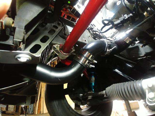
A few "episodes" ago I mounted up the intercooler. Today I started on the plumbing. I bought a generic "intercooler piping kit" from Amazon. It has a selection of alum tubes, alum elbows, silicone connectors both straight and elbows, and a number of T-bolt clamps to put it all together. Because of the size of the turbo outlet, and the throttle body I needed to order silicone "reducing elbows" to adapt to the 2 1/2" piping that came with the kit, but I have all that now, so thought I'd get to it.

The intercooler is mounted in front of the radiator, so I needed to cut a couple holes in the shrouding in front of the radiator. A "sheet rock" bit in a dremel made short work of that (though it did add a little clean up time...). I'm not done with everything on the drivers/intake side of the motor, so without the intake manifold mounted I couldn't do anything over there, but I did get everything finished on the passenger/turbo side. Worked out pretty well! I'm hoping to find someone that can weld a pair of the alum pipes together to eliminate one of the joints if possible, but otherwise I'm happy with how that worked out.


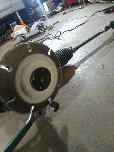
With that done I moved onto the steering. If you remember I'm adapting a steering rack from a Saturn Vue. I'm doing this because the OEM steering rack was going to have to be lowered to fit the motor in place. Doing that would have added quite a bit of pump steer, and I wanted to avoid that. I was already planning to use the electric power steering out of the Vue so I wouldn't have to adapt the Miata power steering pump to the EcoBoost motor, so while I was at it I bought the rack too.

So, I mounted the rack several posts back. Recently, with the help of one of our club members we came up with an adapting solution to get the Miata outer tie rod ends onto the Vue inner tie rods. That worked out fantastic (thanks again)! Today I worked on connecting the Miata steering shaft to the Vue rack.

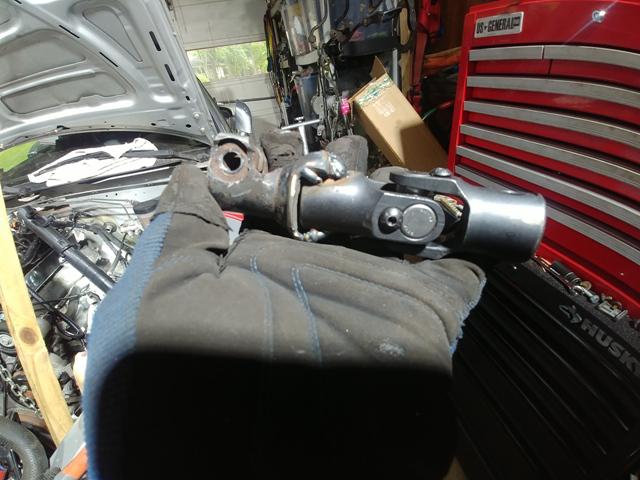
The Miata steering shaft and rack both have a splined shaft. The Vue has a "double D" shaft. This is effectively a round shaft with 2 flats ground into opposite sides. Simple and effective, and as you'll see later, easy to "adjust". Neither the Miata, nor the Vue U-joint were going to be easy to adapt to merry these 2 parts together, so I sourced a new U-joint from, where else, Amazon! It would plug right into the rack, and I'd have to adapt to the steering shaft. With the location of the rack and the steering shaft I test fit the new U-joint. It slipped onto the rack just like it should, and the other end stopped right about at the steering shaft. this should be pretty easy to just cut the Miata U-joint, and weld on the part with the correct spline!

So with the dissected "part of a U-joint" I test fit everything. It's a little tight. I need about 3/4" more room between the 2 shafts to be able to get everything in place.

So, I fired up my angle grinder and "extended" the 2 flats on the steering rack input shaft! that worked great, but the shaft hit the inner workings of the U-joint before I got enough room. So, I fired up the cut off wheel equipped angle grinder (I have 5 angle grinders so I don't have to swap attachments, I just grab the one with the right parts...).


With THAT done it was just a matter of getting the parts lined up correctly and welding them together. After a tack weld, test fit, partial weld, test fit, final weld "test fit", TADA, everything fit!


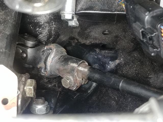
Once everything was installed and tightened up I checked one last time that everything moved freely. I had the right wheel pointed off to the right to be able to tighten the outer tie rod, so I spun the wheel left. the new rack has a little more travel than the OEM Miata rack, and has about 3 1/2 turn lock to lock, so I expected it to turn 2 to 2 1/2 revolutions since I already had the wheels pointed to the right. It only turned about 3/4 of a rev... Huh, that's odd. So, I hop out to see what's hitting what. Everything looks clear, the wheels are still pointed right. So, I hop back in and try again. Nope, wheel won't turn left, so I turn it right. It spins about 3 1/2 revs.... I hope back out and watch the wheels as I spin the steering wheel. Turn the steering wheel left, the wheels point right. Turn the steering wheel right, the wheels point left. SURPRISE!

Yup, you guessed it. the Miata connects the steering in FRONT of the axle, the Vue connects BEHIND the axle!!!

Damn, it was ALL DONE too....

So, a big reminder if you are looking at a project like this, research EVERYTHING.

The really sad part of this chapter is I think the stock rack would work now. When I "needed" the smaller rack I was trying to get the motor as low as it would go. Once it was in the car I found that I had room to raise the motor (about 1") without contacting the hood. This gave me more ground clearance as well, so I had rebuilt the motor mounts last Fall. With that change I think I could now use the OEM steering rack...

I do still have the mounts that I cut off (yeah, just ask Kerry, I never throw ANYTHING away...). So, if anyone knows of an available manual steering rack from an NB Miata, looks like I'm in the market....

TheTick58
TheTick58 GRM+ Memberand New Reader
12/31/20 3:34 p.m.

(9-25-2020)

Time for another update?

With Summer wrapping up, and Fall arriving, I'm seeing if I can get this thing on the road before the convertible weather is all gone...

So, intercooling piping. As stated last time I had a kit of alum tube and couplers. I made all the air connections with that, but just wasn't happy with all the couplers (potential air leaks/separation points). Since I only have a MIG welder, I can't weld aluminum, so at the recommendation of a friend/club member (thanks Steve) I remade the piping with 2 1/2" steel exhaust tubing that I can weld. I was able to connect everything I needed to with 3 parts, so other than actually connecting to other hard parts, there is only 1 "extra" silicone connector (that was needed to be able to install the piping around the other parts). Making it out of steel also allowed me to be able to make a mount for the airflow/temp sensor that needs to be inline.


While I was getting all the intercooler piping done, I also finished the air intake to the turbo. There's another air pressure/temp/flow sensor that goes here, so I just adapted a stock intake elbow from a Ford Edge (e-bay for $30) that would both hold the sensor and an air filter.

Another challenge with the combination of parts that I have is the oil filter would need to be where the subframe is. I more custom/tubular subframe might have eliminated this issue, but that wasn't in keeping with the FRE aspect, so... I went with a remote oil filter option.

The existing oil filter "adapter" bolts to the side of the block (drivers side/rear in my arrangement). There are remote adapters available that simply bolt on in the same location and have NPT connections for hose fittings. I went that route, and have the hoses routed up near the drivers side headlight. There isn't a lot of room next the block, so I ended up moving the pressure sensor that had been on the oil filter housing up to the remote filter location as well.

1 2 3 4

You'll need to log in to post.

Our Preferred Partners
uass8wSM99erp1ze42r2VaHwXkoVaAOaCuwPa0katmJdgIROS2gNo4jjNtazIE3W