
I have completely re-done all the wiring in the challenge car and the last piece is the alternator wiring. I'm trying to figure out what the pinout for the 3-pin plug on the alternator is, but for the life of me I can't find any info online.
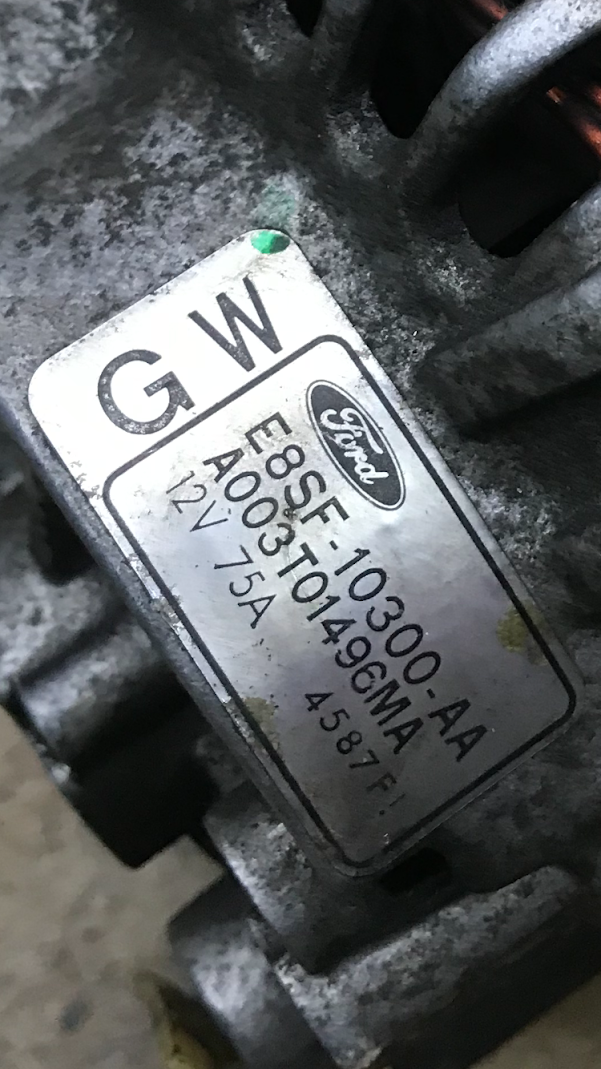
It is a stock alternator for an 88 Ford Thunderbird Turbo Coupe, but so far I have not been able to find any info on it.
Here's the alternator:

Here's the part number:
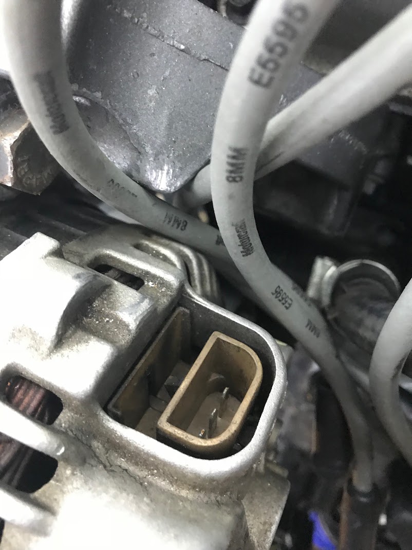
And here's pictures of the connector:
It seems like it's some version of a Ford 3G alternator, since the cooling fan is internal, but everything I have found says that the 3G alternators have a large case (2 holes in between the ribs) or a small case (4 holes in between the ribs), but this has 3 holes in between the ribs... Also the 3G alternators I've seen have the same 3-pin plug, but also a single pin plug as well. This one just has the 3 pin plug.
So...
Do any of you know this alternator to know the wiring pinout?
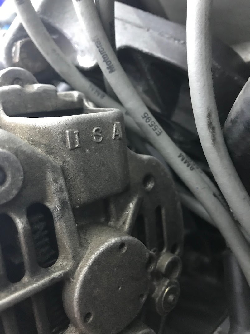
Or, do the I, S, and A markings on the casing near the connector give enough information to derive a pinout?
In reply to volvoclearinghouse :
That could be very useful, thanks!
So according to that, mine would be:
I - Warning Lamp (Probably unused in my case.)
S - Stator Pulse, because Ford. Or possibly battery sense. In either case I'm not exactly sure what to do with that.
A - Battery (Should go to the main terminal going to the battery wire.)
Also, separate question. The main wire from the alternator to the battery, should go directly to the battery correct? I guess it doesn't draw anything when nothing is happening?
I only ask to make sure I put it on the correct side of the cut-off switch. I'm pretty sure I want it on the battery side though, so when you turn the cut-off switch off, everything shuts down. But then the alternator terminal is always hot. As long as that how it's supposed to be, great, I just want to make sure.
In reply to AWSX1686 :
Be careful, if it's anything like the Delco (GM) alternators, the warning light is actually needed. Or, at least, some bit of wire with a nominal resistance to it then connected to the positive terminal via the ignition switch.
Stator pulse- may be able to check that with a voltmeter while turning the alternator to see if it goes on and off. May be able to drive the tach from that.
Hmmm, this seems to show the "I" connection as going to ignition on. Not my exact alternator, but should be close.

S position is the self ignite. Basically tells the alternator is start charging. In my 5 seconds of google-fo, says S to S on the alternator, based on the wiring diagrams I see, and you have a "crappy" 2G version. You could/should just put on a 130 amp 3G in its place with no fab work.
AWSX1686 said:
So I tried messing around with this a bit.
In these scenarios, assume the car is idling:
-ISA Plug not plugged in, no output.
-"A" wire of the ISA plug hooked to the output terminal, output of ~16v.
-Going off of the 2G wiring, I tried putting 12v with a bulb inline to the "I" wire on the ISA plug and there was no change, output still ~16v.
I tested this with both the alternator that was on the car when I got it, as well as the identical alternator off of the parts car.
Any further ideas?
I also have a 3G alternator on order, but if I can make one of these work, that would be better for challenge budget.
Have you tried grounding the Sense (Stator?) per your 5/7 pic? I think both units are just putting out max voltage because the regulator isn't seeing what it needs to see. Both diagrams imply there's another connection somewhere on the alternator...
http://easyautodiagnostics.com/ford/2.3L/alternator-wiring-diagram-1
Or is there another location to connect the S like your diagram above & the one linked here?
On that Ford alternator, the indicator lamp is part of the charging circuit. It lights only if there is a problem with the alternator. There is a resister in parallel with the lamp. When I put the alternator on a tractor I took the whole harness out of the donor car to make it work. You should be able to find the resister value on the wiring diagram of a Ford car of that era. You could try a Potentiometer from I to ground and adjust until it works. .


