1 2
Driven5
Driven5 UberDork
1/23/23 3:35 a.m.

Some of you may recall having seen discussions about this on the FSAE forums from way back, which I'm going to unabashedly steal from. 

So technically I could just say "add sway bars" to interconnet the suspension, but that's not actually what this is about.Sway bars are U-bars that allow the same motion and resist differing motion. U-bars can perform the effects I'll be talking about, but not when connecting laterally (or longitudinally) adjacent wheels as is typically done. But if you reverse the arm on one end, you turn the U-bar into a Z-bar.  A Z-bar allows differing motion and resists similar motion. There are also numerous different mechanisms that can function like a Z-bar that aren't physically a Z shaped torsion bar, but that's a convenient term to use to discuss this idea. So how can you link the corners with Z-bars? Well it has been done numerous times before in the automotive world. 

Packard may be the only one to have done this with true Z-bars (torsion) on their "Torsion Level" suspension. 

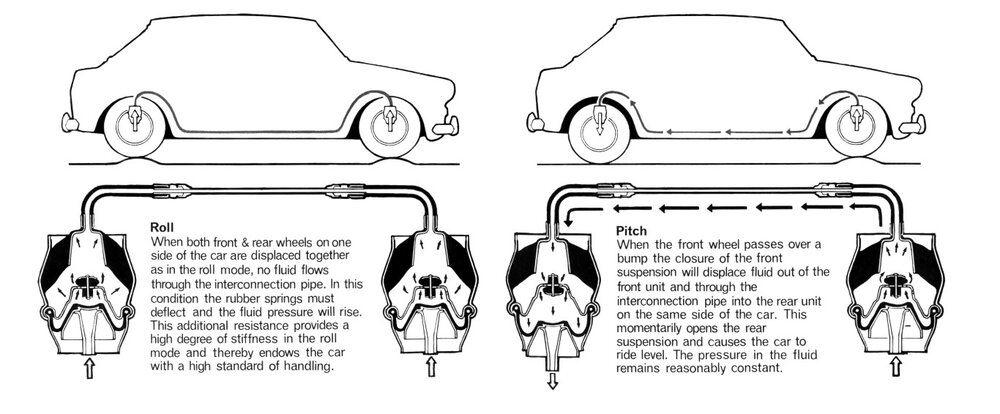
BMC used hydraulics to accomplish the same.

Citroen first did it with coil springs on the 2CV, before doing it hydraulically.

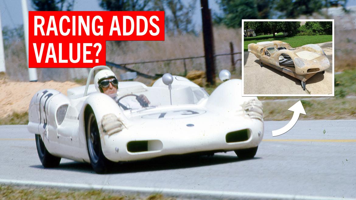
The common theme with all of these cars is that they have been highly regarded for their impeccable ride qualities. This sounds like a 'comfort' thing, and as applied it primarily was. So why am I thinking about it and bringing it up here? Well, because some have also been unusually capable of not sacrificing handling to get that ride quality, and I believe it has further performance benefits that haven't sufficiently been explored as well. The few times these concepts have been applied in professional level racing, they have generally been banned shortly thereafter. But what if at the grassroots level having racecar like performance didn't require a race car like ride, and still utilized the affordability and simplicity of it still being a fully passive suspension?

With a conventional suspension your 4 corner springs have ride, pitch, and roll all hopelessly intertwined. Changing one mode inherently changes both of the other modes. Adding sway bars only provides the ability to independently add roll stiffness. Additionally, once you're not on a perfectly planar surface (let alone if the surface is less than smooth) your carefully balanced tire loading gets all thrown out of whack. This is why it’s so important for corner balancing to be done on a perfectly level surface. The stiffer you suspension gets, the less tolerant it is of these disturbances.

Now let's take a chassis without any springs and throw some longitudinal Z-bars on it, connecting the f/r wheel pairs on each side of the car a la Packard. The f/r leverage ratios determine the stiffness relative to the CG, which is the baseline most people use for handling balance. The problem is that unless your leverage ratios match your weight distribution, which is not typical considered ‘ideal’ for handling balance, just sitting statically the car will inherently pitch forward or back to the bump stops. And even if it is perfectly static balanced, any load change or dynamic imbalance will have similarly disastrous results. As I understand it, BMC was the only one to not add any additional spring elements. Instead they relied only on significantly progressive leverage ratios that biased the (hydraulic) Z-bars against the imbalance. As a result one of the drawbacks was that they were a bit 'pitchy' despite their otherwise good ride and handling.

You can see in the picture above that Citroen added rubber bellows (springing elements) on either end of the 2CV coil spring canister to ‘control’ pitch. On the other hand, their hydraulic system linked everything and used an engine driven pump to compensate, which goes beyond the scope here.

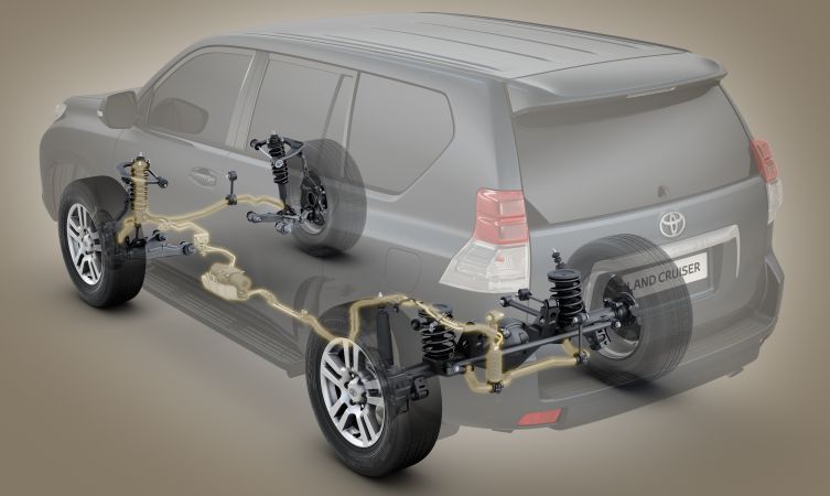
Packard however added a second pair of springs to the rear axle to carry the imbalance.  Here's where it gets interesting through. They added two conventional corner springs to the rear axle. I've seen a sketch of a version with coil springs, but most resources show the torsion bar version (above) that also allowed integrating a load leveling system as well.  However, on a car not likely to see large f/r loading variation, like race cars and 2-seat sports cars, these two springs could technically be replace by just a single (3rd) Z-bar. The 3rd Z-bar would basically just be a pitch-only bar that also carries the relatively small imbalance from the leverage ratio vs CG misalignment. In and of itself, and ignoring motion ratio changes with travel, it would have no direct effect on roll and handling balance though, just as the longitudinal Z-bars would no direct effect on pitch.

The 3 Z-bar suspension would result in a fully functioning 4 wheel car suspension, but the 3rd Z-bar would have to be ‘double acting’ where it is reverse stressed at fully droop. By adding a 4th Z-bar opposite the 3rd Z-bar, it they would be able to be ‘single acting’ like the longitudinal side pair can, which means they’d go slack at full droop. The 4 Z-bar system would also be able to variably add ride stiffness, unlike the 3 Z-bar where ride is carried by the side pair Z-bars.

Now I've only been talking ride, pitch, and roll so far, but there is one more motion mode to consider: Twist.  You know those one-wheel ramp travel articulation tests that 4x4's like to show off with?  Yeah, that's twist.

What does this have to do with pavement performance? Plenty. It goes back to my statement about how performance car suspension setup theory really only holds true on a perfectly planar surface. With a high twist stiffness, as with both independent corner springs and lateral U-bars on high performance cars, as soon as you move one wheel off from planar, the tire loading and handling balance get thrown out of whack. The only conventional way to not do so is how off-roaders do it, which is by lowering your ride, pitch, and roll (spring) rates. But that's bad for performance. Sure any suspension will work if you don’t let it, but what if you could let it work for you rather than against you? By using Z-bars there is as much roll stiffness as you want, but little to no twist stiffness. Non-planar? No problem. Everything from 1-wheel bumps/dips, to cutting across a road crown, to hitting the curbing at the apex, the tire loading variation from all of these plummets. It should be telling that corner balancing also basically becomes a simple function of your f/r leverage ratio, with little regard for how planar the surface is. 

Consider hitting a 1-wheel bump while cornering with a conventional suspension. The load on the tire hitting the bump increases, as well as on the tire diagonally across from it. As it lifts that corner of the car, it reduces load on the tires laterally and longitudinally adjacent to it. This is that teeter-totter feeling you get when turning into an inclined driveway, and is what imbalances everything with a conventional suspension… Including the handling balance at that moment. 

If you hit that same 1-wheel bump with the (3 or 4) Z-bar suspension, that impact load gets transferred to push down on the laterally/longitudinally adjacent wheel pair and pull up on the one diagonally across.  This reduces or eliminates (depending on bump size/speed) the teeter-totter effect, and maintains equivalent tire loading (handling) balance.

Questions, comments, or criticisms?... I mean, those other than “It would be cheaper, faster, and/or easier to just do something conventional.”

Driven5
Driven5 UberDork
1/23/23 3:41 a.m.

Now that you've got some background to chew on, and I'm totally open to answering additional questions or making clarifications on any of that, but the main purpose of this thread is brainstorming about the many different methods for packaging and implementing such a system on an actual car. It can basically be any physical means of connecting them with a spring element somewhere in the mechanism.

I’m also going to backtrack on all of that Z-bar talk, and bring U-bars back into the mix here initially, specifically when configured unconventionally.

A true independent-mode interconnected suspension could also be accomplished with just 3 springs. One for ride, one for pitch, and one for roll. This would be the ‘ideal’ from a tuning perspective. This would actually be possible with 2 U-bars and 1 Z-bar.  Mounting and actuating a longitudinal U-bar between the front pair and rear pair suspensions for pitch would be the ‘easiest’ one. The transvers U-bar acting at the roll distribution point near mid frame, and the transverse Z-bar acting at the CG, would be the bigger challenge to mount and actuate.  So probably not a very viable solution, although I’m open to ideas. I’ve thought of a few, but they get complicated and/or heavy rather quickly.

Another 3-spring method would connect diagonally opposed wheel pairs with what I’d call E-bars. Think U-bars diagonally connecting wheel pairs, with each having an extra mid-ish mounted arm that connect to each other. The problem is that this goes back to linking ride, pitch, and roll together, with the major improvement simply being getting rid of the twist resistance of conventional suspensions.

So that brings  us to the previous examples tying each side together with Z-bars, which is the main difficulty, then adding 1 or 2 Z-bars front and/or rear.  Fundamentally, it would function something like this:

Doing it Packard style with simple torsion bars might actually be the easiest solution, as long as starting with a purpose designed frame. A traditional Locost frame could possibly be modified, but would package poorly on my non-tapered frame, let alone if wanting to adapt to a production based car.  Namely it would probably best use a full-length constant frame taper that the large torsion bars could mount to the outboard face of, as well as either longer control arms or moving the axle back a little relative to the cockpit, which would end up looking a lot like a Locost frame that maintains the taper all the way back:

Next up would be hydraulically connecting the front to rear. This is by far the most common that has been used by automotive manufacturers. Damping can be built into the hydraulic system, or conventional dampers at each corner. However, production hardware is not particularly viable, and DIY solutions leave something to be desired. About the best thing I’ve come up with is off-the-shelf lowrider hydraulic cylinders, and an accumulator for springing. At its simplest, these are actually quite affordable. It might even be possible to convert one to an inverted style strut for use on a production car. Probably the biggest drawback is that they’re also quite heavy for their size, using both a full piston diameter solid steel shaft and thick wall steel body to withstand the pressure spikes. With an accumulator softening the system pressure spikes, might it be possible to custom build a conventional shock conversion with a solid piston, or would it be too much for the body and/or piston seals? The shaft being significantly narrower than the piston in such a conversion could make even relatively small seepage past the seals problematic over time. Motion ratio limitations could also make getting the f/r balance right, as there are limited options to choose from for cylinder diameter. I know that the production units typically used ‘special’ hydraulic fluid, and don’t know how important that might be either.

Another option could be to use air bags. Functionally they’d be pretty similar to hydraulics, but with springing built in, and thus no accumulator needed. It would be considerably lighter, but take up considerably more space and probably be more difficult to package. Bags that will go over dampers like coil springs are available, but with even fewer options and are significantly more expensive. The limited selection of sizes/strengths could likewise be challenging if you have any motion ratio limitations, that might require adding some extra leveraging mechanism to balance it out. Temperature dependence of gas pressure could also be an issue if trying to avoid the cost of a compressor system that can compensate. 

Getting into other mechanical linkages, the steering lock generally prohibits a straight-line connection between the front and rear control arm mounting points, and the similar motion direction of the control arms on the same side of the car needs to be reversed on one end somehow. Bellcranks and push/pull rods could be used for linkages, and maybe even cables when set up in opposing ‘single acting’ pairs. Spring elements could be coils, smaller sections of torsion, full or partial leafs, or whatever else your imagination can come up with. The possibilities for mechanical linkages are are limitless, but the packaging is the opposite. I’ve probably got a half dozen or so of these that I cycle between on a recurring basis. The real trouble is trying to avoid it turning into a Rube Goldberg mechanism.

For example, see starting with the upper left part of the Z-bar sketch above. The two impractically long leafs could be replaced by a (mostly) rigid beam with half of a conventional leaf spring mounted to either end. Keeping the half-leafs at either end, the center pivot beam they're attached to could be replaced by chassis mounted bell cranks, that are tied together with a pull rod or even just a steel cable. Additionally, it technically only needs one spring element, as long as it has the right properties, so you could replace one of the half-leafs with a rigid beam. From there you could replace the other half-leaf with a rigid beam and place a coil spring in the middle of the pull rod or steel cable... Which basically brings it full circle back to a 2CV style setup. 

My current thoughts keep coming back to one air spring at each corner, linked front to rear on each side, combined with a literal z shaped torsion bar front and/or rear.

So… How would you go about this? Which methods do you like or dislike, and why?

PMRacing
PMRacing GRM+ Memberand UltraDork
1/23/23 8:43 a.m.

Subscribing so I can come back later and read when I have more time.  

Jah29
Jah29 GRM+ Memberand Reader
1/23/23 9:09 a.m.

First link i found searching for more info on this.  Lists a few cars that used zbars.


https://forums.autosport.com/topic/100570-z-bar-springing/

GameboyRMH
GameboyRMH GRM+ Memberand MegaDork
1/23/23 9:20 a.m.

This is how one FSAE team did it:

https://www.youtube.com/watch?v=cPouQxfohXA

nocones
nocones GRM+ Memberand PowerDork
1/23/23 11:06 a.m.

I'll have to put a little more thought into it but my initial idea would be carbon fiber 2+" diameter tubes with bonded in aluminum levers on the ends.  I'd run them in parallel down the middle of the tunnel.  

Steel tube probably could work but weight would get large and I'm assuming we are building a smaller light weight car here.  

I thought about Bellcrank and pushrods but at the lengths you'd need buckling would become an issue.  

Pull cables are an interesting idea.  With pullies you could even have the direct act on the suspension.

I'll think about it more and provide some more thoughts 

ProDarwin
ProDarwin MegaDork
1/23/23 11:12 a.m.
PMRacing said:

Subscribing so I can come back later and read when I have more time.  

this

kb58
kb58 UltraDork
1/23/23 11:14 a.m.

There's no free lunch, interconnecting suspension makes it less independent. Taken to the limit, it's like having no suspension whatsoever, while at the same time being much more complex. It's a fun thought experiment, but there's a reason why we don't see (passive) interconnected suspension designs other than anti-roll bars ever coming to fruition.

dculberson
dculberson MegaDork
1/23/23 11:15 a.m.

I read every word and looked at every diagram. It's above my head, but still fascinating.

GameboyRMH
GameboyRMH GRM+ Memberand MegaDork
1/23/23 11:21 a.m.
kb58 said:

There's no free lunch, interconnecting suspension makes it less independent. Taken to the limit, it's like having no suspension whatsoever, while at the same time being much more complex. It's a fun thought experiment, but there's a reason why we don't see (passive) interconnected suspension designs other than anti-roll bars ever coming to fruition.

A few cars have had them - the McLaren P1 and a few other models have their FRICS system (passive but electronically adjustable), and then there were some oddballs that had hydraulic interconnected systems as well, like the Citroen DS, Minis had BMC Hydrolastic suspension as an option, and Toyota put their XREAS system on some 4x4s.

Trent
Trent PowerDork
1/23/23 12:21 p.m.

All I have to add to this discussion is that the cars I have driven with fully interconnected suspensions (Citroen, Rolls Royce, Bentley)  Have been the most unnerving cars I have ever driven. Wallowy, vague and disconnected. 


Mini's with hydrolastic are the best but I still prefer the feel of a dry mini. That is probably just a case of that is what I am used to.

Asphalt_Gundam
Asphalt_Gundam HalfDork
1/23/23 1:01 p.m.

I could be way off but:

Equal tire loading....simple as all 4 wheels connected hydraulicly....or more easily via air? Would make even pressure loading on all 4. Would ideally require matching motion ratios at all. Pitch and roll would be un controlled though...So conventional swaybars could fix the roll. Pitch needs a front to rear sway bar then which pretty much establishes the need for independent front/rear vs side to side control.

So...all 4 hydraulically connected but......utilizing 4 independent circuits. LF to RF, LF to LR, RF to RR, LR to RR. Bump at LF will send it's increased pressure to RF and LR on separate circuits but the extra load will be shared between the 3 wheels. Could go further with another circuit to the RR but from an opposite side of a piston so that it would at the same moment reduce load on the RR when LF is in bump. To visualize the opposite corner wheels are bottom of the hyd cylinder connected. Piston in the middle is whats hooked to the wheel and cylinder is chassis mounted. The wheels across from and same side to the wheel in bump are hooked to the top of the cylinder. This seems like it would sort out equal loading of the tires and sets up a system that will "fight it self" in a way that will control pitch and roll. 

However, my gut says hydraulic fluid would be to harsh of a movement and pretty much just lock everything unless some serious design went into the system in regards to fluid flow metering, if its even possible. Air seems like a much better application as it is compressible and if metered (again some serious design required) will allow independent movement of each wheel. 

Now to poke holes:

So the car is loaded up near or at max grip in a corner. The apex curb gets clipped and one wheel is affected with the side effect of transferring its load (relatively small being the inside) to the outside wheels, possibly overloading them and results in running wide on exit. Additional effect here of the front or rear swaybars coming into play as trying to lift/reduce load at the front outside and inside rear. The decaying forces of twisting those bars does reduce the total force transferred though.

Now with any of the systems laid out by OP and above in this post we end up with an apex curb'd wheel that is now directly transferring its force to 2 or all 3 of the other wheels. Apart from a maintained ride height are we gaining anything? Or is that load transfer then going to upset any of the other wheels more than a conventional system?

Seems like we would want the curb/bump wheel to transfer zero load to any of the others so that they can maintain a happy, stable grip. I feel like a relevant conversation from conventional designs is big spring vs big bar in circle track racing. I've run my car with both style setups and I can say that while both work, big bar/soft spring is much more forgiving when curbing comes along. In my case it also has a much larger tuning window, especially with utilizing the shock/damper adjustments.

Following that thought process then perhaps a 4 corner soft spring setup with both horizontal and longitudinal torsion bars is a potential solution. But its just a conventional setup with the addition of a fore/aft torsion bar on each side. The red flag I see is unloading the rear on the brakes during dive...unless Z bar...but that would encourage pitch vs reduce it but more likely to maintain equal tire loading.

All very interesting as a mental exercise but... is this an overcomplicated solution for problems that existed 50+ years ago that modern spring/shock technology has already solved? I suspect the electro-mag suspensions that a few of the OE use is that solution for independent wheel motion while maintaining equal loads and controling body movement

Driven5
Driven5 UberDork
1/23/23 1:08 p.m.
kb58 said:

There's no free lunch, interconnecting suspension makes it less independent. Taken to the limit, it's like having no suspension whatsoever...

Suspension independence is a myth. The stiffer the springs get, the more individual corner suspension events effect the other 3 corners. I'd argue that the true measure of suspension 'independence' is through tire load variation.

In this regard, traditional corner sprung suspension at the same pitch and roll rates (even ignoring that 'indpendence' killing sway bars would be required to achieve this) as on a fully interconnected suspension will inherently have far worse tire load variation over one-wheel suspension movements. By that measure, I'd argue it's actually less independent. Taken the same extreme, with infinite pitch and roll rates, the interconnected suspension will still comfortably traverse one wheel events with minimal tire load variation. The corner sprung suspension will do no such thing.

I won't discount the additional challenge of implementation, which is what I believe is the main (aside from lack of understanding) hindrance to wider spread acceptance, and is the entire reason for the existence of this thread.

Driven5
Driven5 UberDork
1/23/23 2:25 p.m.

In reply to Asphalt_Gundam :

Remember that anything that deflects the suspension will inherently cause load transfer on any suspension. So there is no way around that. The fully interconnected suspension is not reallocating its static load to the other wheels though, like conventional springing does, but rather only distributing that additional load equivalently (to static ratios) among all the wheels.

Let's flip it around and see what we would need to do to create the same effect to the tires if we were cornering on a level surface, as is happening during that instant of the inside front corner impact. For the interconnected suspension, there is no difference. For the conventional suspension, hitting the front inside bump would be the same as raising the inside front and outside rear spring perches while lowering the outside front and inside rear spring perches during cornering on a level surface.

Then when the rear wheel hits the bump as the front wheel is back off of it, the opposite happens. For the interconnected suspension, there is still no difference. For the conventional suspension, hitting the rear inside bump would be the same as lowering the inside front and outside rear spring perches while raising the outside front and inside rear spring perches during cornering on a level surface.

The instantaneous suspension balance is getting thrown all over the place. All of our damper tuning performance (and complexity/cost inducing technology) advancements have basically been driven by trying to mitigate the symptoms of the problem... What I'm talking about is trying to effectively eliminate the cause problem. In doing so, it should also allow for substantially reduced damping needs resulting in the simplified dampers eating less of the cars kinetic energy.

You're on the right track with softening the 4 corner suspension and making up for it by increasing the longitudinal and lateral interconnection. The less the 4 corners contribute, and more the interconnection contributes, the more effectively it should work... Continuing all the way down to the 4 corners dropping to zero contribution, and putting it all on the interconnections.

As described, you're basically just trying to use the 4 corners to provide pure vertical (all 4 wheels in unison) ride stiffness while letting the longitudinal and lateral interconnections control pitch, roll, and LLTD. But with the way the longitudinal and lateral interconnections handle single and multi-wheel impacts, pure ride stiffness becomes a secondary concern that only applies when hitting bumps that are exactly at 1-wheelbase apart. So there is no reason not to have the lateral and longitudinal interconnections pull double duty and be carrying the ride load too.

Also, in regards to the harshness of a hydraulic system, an accumulator basically is just adding an air-spring into the system, and could effectively be tuned to provide the same rates as air springs. The advantage is that the damping can be built into the system, while the air-springs would still need additional dampers.

kb58
kb58 UltraDork
1/23/23 3:23 p.m.
Driven5 said:
kb58 said:

There's no free lunch, interconnecting suspension makes it less independent. Taken to the limit, it's like having no suspension whatsoever...

Suspension independence is a myth. ...

Correct, so I'll change that to "separately suspended suspension is the most 'independent'; everything else is less so."

Driven5
Driven5 UberDork
1/23/23 4:46 p.m.
kb58 said:

Correct, so I'll change that to "separately suspended suspension is the most 'independent'; everything else is less so."

I'll agree with that statement for a single suspended wheel viewed in isolation. I'll disagree with that statement for a system of 4 suspended wheels all acting on each other through a single body. What happens (force/load wise) at one wheels is more dependent on what the other 3 wheels are doing in a conventional 'separately suspended' suspension than it is in an interconnected one.

Even if sticking with the single corner in isolation view of 'independence', what leads you to believe that this lack of consideration for how forces at one corner affects the other corners is the most desirable (ideal) state for controlling the body motions and load transfer across all of the tires?

GameboyRMH
GameboyRMH GRM+ Memberand MegaDork
1/23/23 5:14 p.m.

Independent suspension is definitely a bit of a misnomer, the only thing that's really independent about it is the camber curve relative to the chassis, in terms of the load on the wheels the only improvement is that movement on one wheel doesn't directly translate into movement on one on the other side through a solid axle. A highly independent suspension isn't necessarily a good thing either, after all solid axles are still preferred for rock crawling and McLaren FRICS is magical on track despite being arguably the least independent suspension ever conceived.

nocones
nocones GRM+ Memberand PowerDork
1/23/23 5:36 p.m.

I'm just not sure I see how it can work inherently better without active management.  The Williams system obviously was amazing and definitely worked, hence the ban.   I'm not sure Anything less then that will work any better then a traditional Spring/shock for each corner, Antil Roll bar at each axle system.  I'm also not sure it functionally would work different.  You may be absorbing the force of 1 wheel displacement in the adjacent wheels (Same side of car, Same Axle) but the result to the car would seem to still be a load change at the cross car wheel, which seems to be the situation you are attempting to avoid.  

What you would want to have happen is that wheel to just magically move with no force change to accommodate the road surface.  I don't think that is possible without an active system.  

3rd link suspensions are becoming more common but that is primarily driven by a changing dynamic vertical force on the axles and not due to some inherent benefit given.  The addition of the 3rd link does allow the decoupling of ride and roll which allows for lower single wheel ride rates but you still generally see an overall traditional setup.  And even with that advantage their use on non-aero cars is still fundamentally a-typical due to the increased weight and tuning complexity.  Traditional results in faster lap times until the ride rates get so out of hand to resist the Aero loads that performance suffers due to a complete lack of compliance (See my car that I am currently developing a 3rd link and swaybars for because the rear spring rates are out of hand).

Kyle Engineers on Youtube had a video about a fully decoupled suspension design and I don't currently remember what the takeaway was.  I'll pull it up and watch it again to see where he thought it was going.    


This is still very very interesting stuff and I am reading to try to get my thoughts on it changed.  I am now more intrigued about the idea of a suspension that basically treats all 4 sides of a car like a 3 damper+T bar arrangement that is common on full areo cars today.  So basically adding 2 T bars and 2 additional shocks that treat the longitudinal car loads like the individual axle loads.  IIRC this is sort of what Kyle Engineers was discussing.   Is there value in this or does the ability to reduce ride rate no longer help?

Driven5
Driven5 UberDork
1/23/23 5:39 p.m.

In reply to nocones (1st post):

I'm looking at things from the GRM level. So really focusing on off-the-shelf components and DIYable solutions.

For torsion tubes, I'm not sure that CF would be on the docket. For a Locost-esque car, the longitudinal steel torsion tubes could probably be 1.25-1.5 DOM, but would weigh in the neighborhood of 20+ pounds each.

Off the shelf pulleys for appropriately sized steel cable would probably be more expensive,  and more difficult (larger diameter) to package, than treating the cable like a pullrod and just connecting the bellcranks via cables. On the other hand, direct actuation with the bellcranks can start to uncomfortably increase the joint count. There are a LOT of ways they can be implemented though.

Last I was thinking about cables, I was also looking at beam axles on one or both ends, which affects methods of connection and actuation as well. Since I've been gravitating toward a lateral control arm variation on the torsion rod trailing arm suspension concept, which would use a more conventional lower 'a-arm', it's probably worth revisiting some of the ideas that may not have been as conducive before.

Driven5
Driven5 UberDork
1/23/23 6:13 p.m.
nocones said:

You may be absorbing the force of 1 wheel displacement in the adjacent wheels (Same side of car, Same Axle) but the result to the car would seem to still be a load change at the cross car wheel...

The distribution of the force flows through all 4 wheels. The displaced (up) wheel pushes the adjacent wheels down to prevent unloading them. Pushing down on the adjacent wheels pulls up on their mutually adjacent (diagonally opposed to the originally displaced) wheel to prevent overloading it.

A true fully-decoupled (heave, pitch, and roll) suspension is most beneficial for high downforce cars. Otherweise the 2 lateral x 2 longitudinal 'z-bar' arrangement can likely simplifies the implementation, with the caveat being that heave remains coupled to a combination of the pitch and roll rates

Strizzo
Strizzo PowerDork
1/23/23 7:14 p.m.

also take a look at the toyota KDSS system used on Land Cruiser, 4Runner, and Land Cruiser Prado/GX460/470


Driven5
Driven5 UberDork
1/23/23 7:31 p.m.

Here's an example of an FSAE/FS team that used an interconnected (decoupled) system:


Jah29
Jah29 GRM+ Memberand Reader
1/23/23 7:37 p.m.
Driven5 said:

Also, in regards to the harshness of a hydraulic system, an accumulator basically is just adding an air-spring into the system, and could effectively be tuned to provide the same rates as air springs. The advantage is that the damping can be built into the system, while the air-springs would still need additional dampers.

Enjoying this.  I have very little to add.  I do know that the hydraulic mclaren road car system does use an accumulator/reservoir to keep the system pressure under control.

Oapfu
Oapfu GRM+ Memberand Reader
1/24/23 12:27 a.m.
  • Driven5-- thank you for starting this thread!
  • this may or may not be just semantics: IMO the end goal is a "mode-decoupled" suspension (able to separately adjust the vehicle's response to roll/pitch/heave/warp); "interconnected" suspension is the method to get to this goal, but "interconnected" can describe anything from one sway bar all the way up to achieving full mode-decoupling.
  • for realistic-budget DIY, I see two approaches: figure out how to make a mechanical system functional; or, figure out how to make a hydraulic system have an acceptable tradeoff based on "strong, lightweight, cheap: pick two".  Hydraulic systems exist and have been functional, so IMO the only reason to mess about with mechanical linkages is the possible hope for lower cost and less mandatory precision machining.

If you want all of the maths, here are a few links.  There are many other papers but I have not found 'em online for free; I also have not looked for a  while.  I collect .pdfs the way other people collect boxes of random parts for cars they don't own... and for years I've put off starting the 20k read-thrus I'll need to start understanding this stuff.

This is the Kyle Engineer vid which nocones mentioned, Kyle starts with mechanical linkages and ends up at ETH Zürich's FSAE hydraulic setup (which is the YT link GameboyRMH posted much earlier).  Watch Kyle's vid, then rewatch the ETH vid from 11:33-25:37 until you can explain the system all on your own.  Matlab has blog post1 and post2 taken from the ETH .ppt slides.

Driven5
Driven5 UberDork
1/24/23 2:24 p.m.

In reply to Oapfu :

I've seen the Kyle Engineers and the ETH videos before, but they're great to help fill in the blanks I've not adequately covered for others here too... Although I wish Kyle Engineers followed through with correcting the mechanical linkages to decouple roll and warp before abandoning it and jumping to the hydraulic 'equivalent'. The papers are new to me though, so having that all in one place is a great resource. Thanks!

Yes, mode decoupling is the goal. To fully decouple all 4 modes, hydraulic is pretty much the only reasonable way I've seen to go But the cost and complexity of doing so are a substantial barrier to (grassroots) entry. However, I'm also not convinced that it's equally important to fully decouple heave for a non-aero car, as it is roll, pitch, and warp from each other. That's why I've been largely discussing the 2x2 (lateral x longitudinal) system to simplify the necessary interconnections, while still effectively getting all of the major decoupling benefits. The front and rear lateral pairings are relatively easily implemented, leaving the left and right longitudinal side pairings as the primary challenging connection to make. For that, I have not seen a compelling argument for the pros/cons of hydraulic vs pneumatic, or even mechanical.

1 2

You'll need to log in to post.

Our Preferred Partners
9xLdRxd9tO36MsD8Rmz9TefNC5X4RkmAJa2cKo4tajs1Ih8qFYbmhkYHArbmFCPx