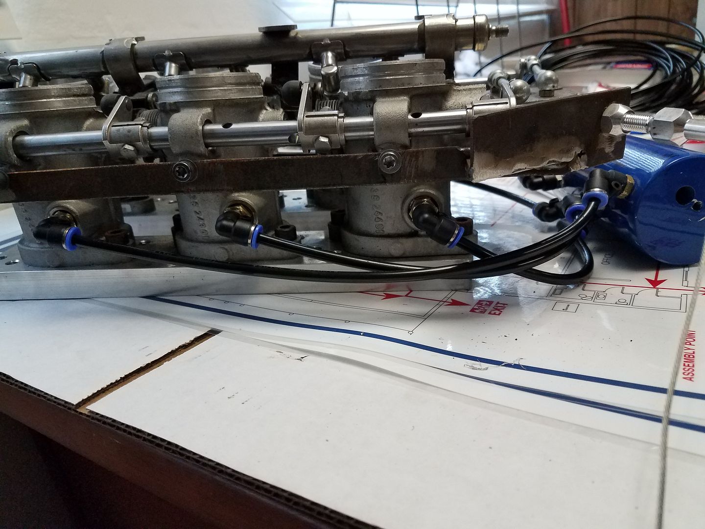
Ok, so I am building an airbox for my ITBs....and am now contemplating the air intake into the box(getting kinda ahead of myself) and I want to integrate a MAF sensor but find myself kinda boxed into a corner where I need to run 2 inlet tubes into the box...so with 2 inlet tubes I suppose I would require 2 MAP sensors like this picture of a BMW M5 airbox:

So my question is does anyone know if MS(I am using MS3X) has support for adding the sum of 2 MAP sensors together? Or is there some other foolery I can come up with to get an accurate measurement from 2 inlets with 1 MAP sensor?
MAP is different from MAF. I don't think the manifold pressure will care if it's one one bank instead of 2.
Also, the MAF is before the throttle body, MAP is after. The challenge with MAP with ITBs is getting a good, consistent vacuum signal. Folks often need to make a little jumper tube/manifold across all the runners to get a good average signal.
There is only one Manifold Air Pressure (MAP) and it is measured AFTER the throttle body. The picture you posted is inaccurate as the sensors you see in those two air intakes are Manifold Air Flow (MAF) sensors. Assuming you are setting up your MS3X as speed-density, you don't need MAF, only a single MAP and it has to be between the throttle body and the intake ports of the engine.
Yes, they are MAF sensors(just mistyped that 2nd time). I would like MAF though because it will make tuning the Ti-VCT infinitely easier, trust me, if I didn't feel like I needed it there is no way I would bother running one(probably wouldn't even bother building an airbox)
In reply to Brotus7 :
I have the solution for a consistent MAP signal almost finished.
I have no personal experience, but everything I have ever read about trying to run ITB motors in Speed/Density using a MAP sensor says don't do it. The throttled volume on any individual cylinder is so small that you don't get a stable reading and it's a nightmare. MAF or alpha-N are usually the control logic systems of choice.
I haven't tuned a MAF car in megasquirt either, but I would think that since each bank of 4 cylinders is breathing through a single MAF, the two identical MAF sensors had really better be returning the same values. If that's true, maybe you can just have the MS read one of them and double the value?
I'm not a circuits person, but in previous questions on how to build a circuit, people here have helped out.
So what you are looking for is a way to take two 0-5V inputs, and just average them- which makes sense, since all 8 cylinders will be feeding from one common intake manifild fed by these two MAF sensors.
Again, not being a circuits person, that should be able to be done via some circuitry- I just have no idea how.
But I have done some very minor Arduino, and that will certainly be capable of taking two 0-5V inputs, average them together, and then shoot out that answer. On that, I would suggest to find one that uses more than just small pins and that you can solder both the input and the output wires. But a simple code like that will run really fast, since there's virtually no code to perform that action.
Since the MS is expecting a 0-5v input for MAF, then you will end up doing the sum math in the MS calibration.
In reply to alfadriver :
Electronically, averaging two 0-5V signals is pretty trivial. Just need an op-amp and a few discrete components. Output would be a 0-5V signal that is the average of the two inputs. That signal could be the single MAF input to the Megasquirt.
You can input two MAFs into the MS, but likely only one to read load. You could log both and create your MAF transfer function based on the predicted average. If both intake tracts are identical, I would likely just run a single MAF and assume the airflow is doubled.
I wouldn't bother with a MAF, its a bit of a hack to get one setup on MS, you'll need a single intake tube and ITB/Blended-mode works quite well.
Brotus7 said:
MAP is different from MAF. I don't think the manifold pressure will care if it's one one bank instead of 2.
Also, the MAF is before the throttle body, MAP is after. The challenge with MAP with ITBs is getting a good, consistent vacuum signal. Folks often need to make a little jumper tube/manifold across all the runners to get a good average signal.
ITB Mode
http://www.msextra.com/doc/pdf/html/Megasquirt3_Setting_Up-1.5.pdf/Megasquirt3_Setting_Up-1.5-64.html
I think you may run into problems using hardware averaging of the two MAF signals. MAF transfer functions aren't linear. Most ECUs which use MAFs have a VERY large table that is a voltage to mass flow look up.
burdickjp said:
I think you may run into problems using hardware averaging of the two MAF signals. MAF transfer functions aren't linear. Most ECUs which use MAFs have a VERY large table that is a voltage to mass flow look up.
Why back when (in the late 90's) there was a trophy truck that had dual MAFs, and an averaging board- it worked quite well- winning the Baja 1000. It ran a whole lot better than when they unplugged one and bypassed the average circuit. While in the whole, the transfer function isn't linear, if the set up is reasonably equal, the range where you are doing the average is linear enough. Seems to me that it would be a far more robust solution than the alpha-n calibration would be- even if that ran really well....
edit- one other thing one can do with the arduino is take both transfer functions, add the two mass inputs together and then send that out to the MS- which would have a 3rd transfer function that is the same as the arduino MAF to volgage output.
Is the use of two MAF sensors done because of volume or packaging? Could you use one large MAF sensor and package it differently?
I forgot, yet another vote for no nonsense and use ITB mode. Even if MAF can work I don't think the view is worth the climb having done both.

Well, MAF is a matter of practicality more than anything. The LAST thing I want to do is have to wire 2 more inputs into the engine....but its DOHC v6 Ti-VCT....both intake and exhaust cams are VVT. This makes tuning without MAF a huge pain, I have to tune this thing from scratch, so MAF makes that far easier. As for why it needs 2 air inlets...
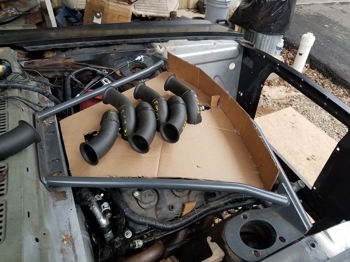
This cardboard template is a visual representation of the packaging I am working with(I will make the fiberglass plug out of styrofoam). There are 2 possibilities for air inlets here:
1. A cowl entry through a flat rectangular filter. This would be easy...but would provide such a large opening into the airbox a MAF sensor has little to no hope of reading accurately...and there simply isn't enough room to neck it down post filter to a standard circular hole.
2. Dual entry coming from in front of the valve covers sweeping up from below the shock tower brace into the front corners of the airbox.(Cant be center entry simply because the cooling system pipes don't provide enough room)
3. This is a weird one: Using a carburetor circular filter on top somehow with a bellmouth in the center feeding into the airbox(not very practical since it would require a hood scoop larger than I want to use)
I have done dual/quad VVT on lots of engines with no MAF. You use TPS for cam load axis anyway.
Paul_VR6 said:
I have done dual/quad VVT on lots of engines with no MAF. You use TPS for cam load axis anyway.
It's curious that you have such objection to MAF. In my career, I've always found that MAF cars are far easier to calibrate. Far, far easier.
And for a VCT axis, why in the world would MS use TPS for that? It's physics are more about air flow than throttle position. OEM's use load to set VCT.
Just because you can doesn't mean it's the best way of doing it. Alpha-N has a lot more required imputs to make it robust to more conditions.
I am open to the idea of ditching the MAF, I just don't want to end up in a situation where I have to tune the engine multiple times if I switch velocity stack length or something, but it ends up taking 6 months to hammer out a good tune each time(I won't have access to a dyno for dyno tuning after all, I will be stuck with just the in-car tools like wideband, pyrometer, etc.)
In reply to Wicked93gs :
If you are running MS, I would plan on the WB being a permantent install. All modern cars have been running with those as the primary input for over a decade now, and they are the best for real feedback.
Not really an objection, I just don't see the appeal on a non OEM setup. Seems to over complicate things a bit with not a huge amount of gain. Every MAF car I've done from scratch seems to take longer than any SD or Alpha/ITB setup, at least the first time. The MAF data can be ported over the more identical setups you can do, moreso than SD/Alpha/ITB. For a project like this it could make sense if you have infitite time to play with it. I am usually given some budgetary limitations on tuning time and I can get to the end faster without a MAF.
Edit: totally agree on the full time wideband, and one per bank, period.
In reply to Paul_VR6 :
I don't see it that way- send the two intake's out to get flowed and measured, and you have the MAF transfer function. Also flow the injectors.
Then set one of the two to be the gold standard- given the input to the code, it almost always makes sense to make the injectors the gold stadard, and then tweak the MAF transfer function to keep any closed loop corrections to a min.
With SD and AN set ups, the amount of fuel will change everytime the cam is changed- as the air flow changes with every cam change- so you can get totally different answers with the same input except for cam position. Whereas if you are measuring the MAF, you already know that, and the injection is taken care of as you sweep the cams. I see that as a major reduction in time it takes to tune it. Heck, with MAF, finding the cam timing that flows the most air is pretty easy- you'll see that immediately.
I do plan on a permanent install of the wideband(s)(But a wideband to me is still an in-car tool regardless of whether or not its permanently installed, along with a pyrometer).
Each inlet tube should flow the same into the box(it will be a mirrored setup like the orginal BMW pic)..once in the box the airflow may change though...I would expect the stack at the passenger side rear to possibly flow less...it comes fairly close to the wall of the box(will try to reorient some of the horns before the end(or make new ones better suited to the task)


